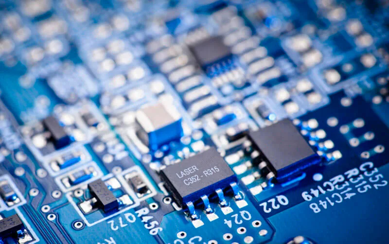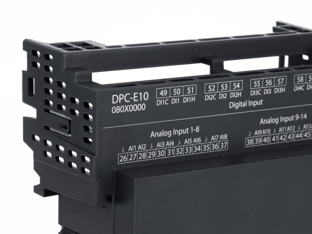
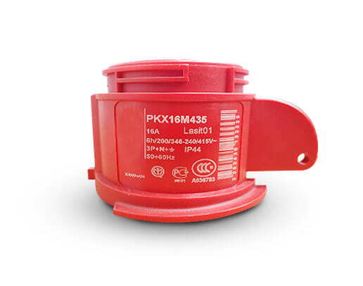
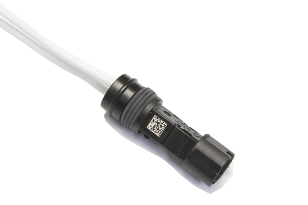
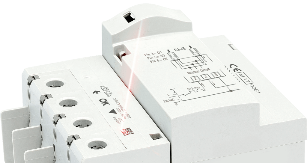
Marking electronic components represents one of the most complex challenges in modern industry. Plastic housings, connectors, switches, and protective devices require permanent, readable codes that comply with traceability standards, but must be applied to small surfaces, heat-sensitive materials, and irregular geometries. In this context, the choice of laser source and marking system becomes decisive not only for the quality of the result, but also for the efficiency of the entire production line.
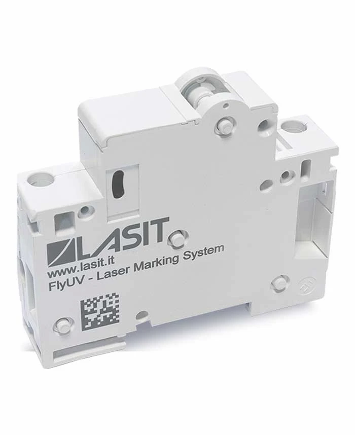
UV and green lasers have established themselves as reference technologies for cold marking of technical plastics and polymeric materials used in electronics. Unlike conventional infrared lasers, these sources operate with shorter wavelengths that allow controlled ablation of the surface layer without generating thermal stress. The result is sharp, permanent, distortion-free marking, even on millimeter-sized components or those with delicate surface finishes.
Why UV and green: operational differences and selection criteria
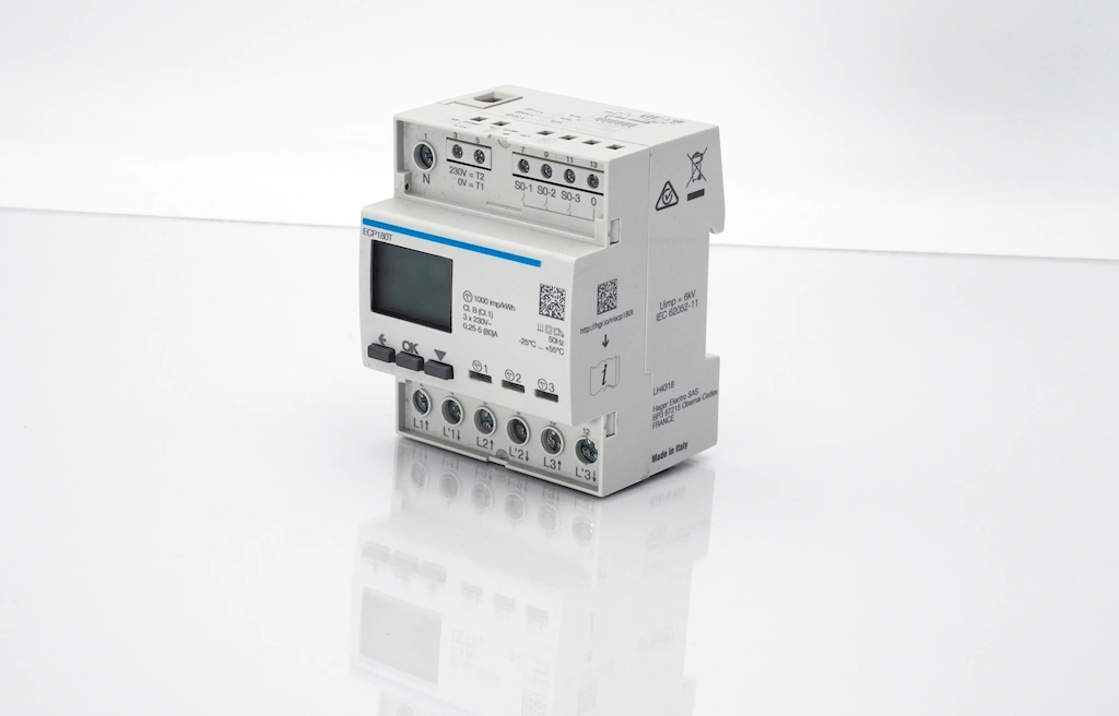
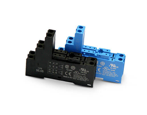
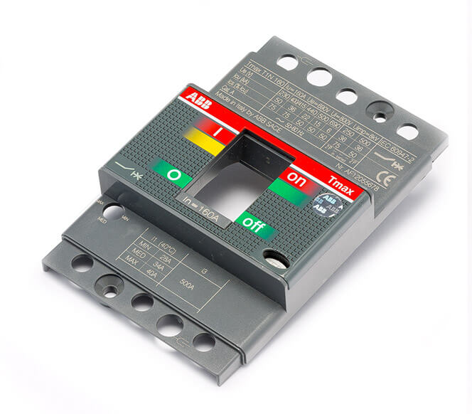
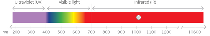
UV lasers, with a wavelength of 355 nm, act through a photochemical process that breaks the molecular bonds of the polymer without melting the material. This mechanism allows clear, transparent or highly reflective plastics to be marked with high contrast and defined edges. They are particularly suitable for materials such as polycarbonate, ABS, polyamide and engineering resins used in modular device enclosures, differential switches and electronic control units.
Green lasers, with a wavelength of 532 nm, are an effective alternative for applications requiring higher process speeds while maintaining cold marking. While not achieving the absorption accuracy of UV, green offers higher peak power and shorter cycle times, making it ideal for high-volume production on pigmented plastics or composite materials. The choice between UV and green depends on three main factors: type of polymer, contrast required, and production cadence. In general, UV ensures the highest visual quality on light-colored and transparent materials, while green optimizes timing on dark or additive-laden plastics.

Thermal management remains critical, however: even with cold sources, the average power and repetition rate must be calibrated to avoid local deformation or unwanted color changes. On components with thin thicknesses or thin walls, it is critical to limit energy density to prevent residual heat from propagating through the mass of the part.
Process parameters and operational setup in electronic component marking
Configuring a laser system for marking electronic components requires optimizing several parameters depending on the material, geometry and code to be applied. The main elements to consider are average power, pulse repetition rate, scanning speed and fill density for solid areas.
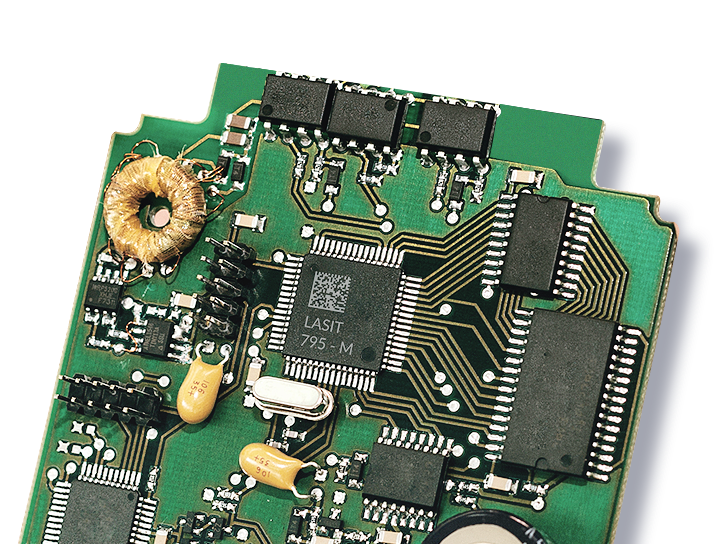
For technical plastics such as polycarbonate and ABS, typically used in modular device housings, reference values with UV lasers are in the range of average powers between 3 and 8 W, repetition frequencies between 30 and 80 kHz, and marking speeds between 800 and 2000 mm/s. With green lasers, the average power can go up to 10-15 W while maintaining similar speeds, with generally higher frequencies to compensate for lower absorption efficiency. The size of the focal spot, typically between 20 and 35 µm, determines the final resolution and readability of matrix codes with modules less than 0.3 mm.
One aspect that is often underestimated is dynamic focus management. On components with curved or sloping surfaces, systems equipped with optical autofocus or software height compensation make it possible to maintain consistent marking quality along the entire contour of the part. This is especially relevant on enclosures with internal ribs, docking clips or mounting areas that create height variations of even several millimeters.
Repeatability of positioning is equally crucial: in automated lines, the part may be presented with position tolerances of up to ±2 mm. To ensure that the code is always applied in the correct area, vision systems must be integrated for automatic part recognition and real-time marking position correction.
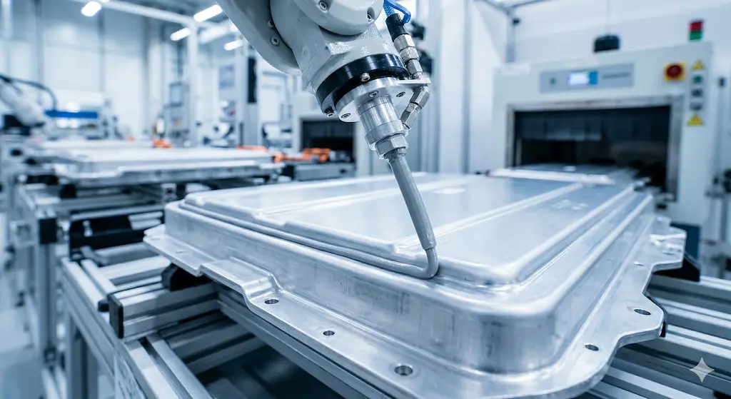
Online integration: from stand-alone machine to robotic cell
In real manufacturing contexts, laser marking is not an isolated operation but an element of a larger sequence that may include stamping, assembly, electrical testing, and packaging. The ability to integrate the marking system smoothly into the existing line is often more crucial than pure laser performance.
There are three main integration architectures. The first is the manual or semiautomatic marking station, where the operator places the component on a dedicated jig and starts the cycle. This solution is suitable for batch production, prototypes or large components that require assisted manipulation. The second is in-line integration with conveyor, where the laser system is installed on a belt or chain and marks moving or temporarily stopped parts. This configuration is common in high-cadence assembly lines, where each station has a defined cycle time and marking must occur without slowing down the flow.
The third architecture is the robotic cell, in which an anthropomorphic robot or SCARA picks up the component from a magazine, presents it to the laser for marking, and deposits it on a belt or in a container. This approach offers maximum flexibility, allowing multiple surfaces to be marked or complex geometries to be handled with orientation changes during the cycle.
At LASIT, we observed that the choice of integration model depends not only on the production cadence but also on the variability of the product mix. Lines dedicated to a single component may use fixed jigs and optimized cycles, while multi-product lines require vision systems and recipe management software for quick changes without mechanical retooling.
Powermark: modularity and centralized control for multi-laser lines
When production spans multiple lines or requires simultaneous marking on several stations, distributed management of laser systems becomes an operational requirement. The Powermark model is designed precisely to meet this need, offering a compact and highly integrable marking platform with software architecture that allows up to five laser units to be controlled from a single industrial PC.
This centralized configuration dramatically reduces IT management costs, simplifies software upgrades, and facilitates production supervision. Each laser head can operate independently on different stations, maintaining data synchronization and traceability through a single interface. The operator can monitor the status of all units, check marking counters, manage recipes, and intervene in case of anomalies without having to physically move between stations.
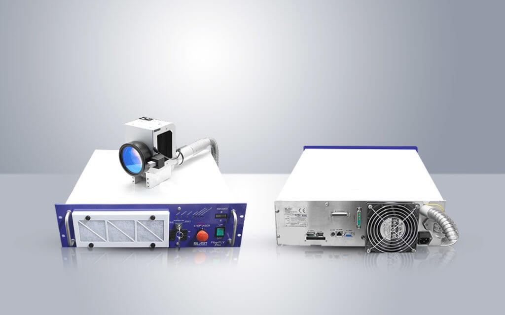
The Powermark’s compact size facilitates installation even in tight spaces or in retrofits of existing lines. The small footprint allows the laser head to be positioned close to the work area, reducing the length of the control cable and improving the responsiveness of the system. This is especially useful in robotic cells where space is limited and each component must be optimized to avoid mechanical interference.
Hardware modularity supports custom configurations based on application specifications: UV or green lasers, optics with different focal lengths, integrated vision systems, and digital interfaces for communication with PLCs, robots, and supervisory systems. The ability to add or replace components without changing the entire system ensures scalability over time and reduces downtime for maintenance or technology upgrades.
Integrated computer vision: self-centering, verification and qualitative grading
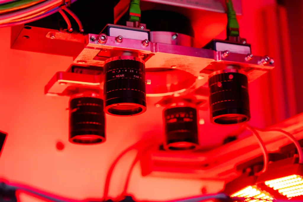
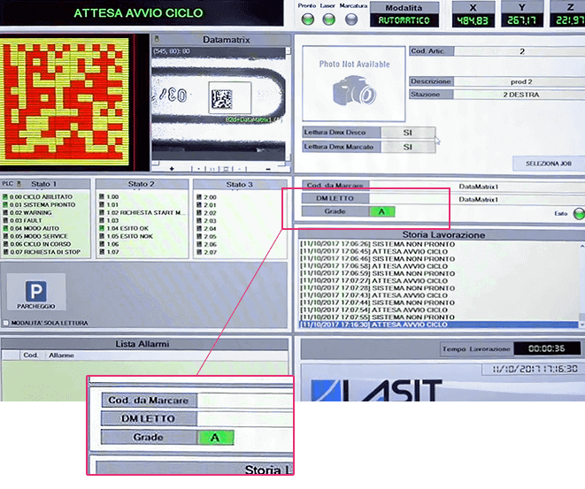
One of the distinguishing features of Powermark is the native integration of machine vision cameras, which transform the system from a simple marker to an intelligent quality control unit. The cameras can be used for three main functions: self-centering of the component, verification of presence and correct orientation, and quality grading of the marked code.
Self-centering exploits pattern-matching algorithms to recognize the actual position of the part relative to the laser reference system. Once the image is acquired, the software calculates the deviation from the nominal position and automatically corrects the marking coordinates. This allows positioning tolerances of up to ±3 mm to be compensated for without requiring precision mechanical jigs or passive centering systems.
Post-marking verification takes place immediately after the laser cycle: the camera captures the newly made code and verifies it according to ISO/IEC 15415 standards for matrix codes or ISO/IEC 15416 for linear codes. The system calculates parameters such as symbol contrast, modulation uniformity, axis defects, and content decoding, assigning a grading from A to F. Components with grading below a preset threshold can be automatically discarded, signaled to the operator, or remarked with corrected parameters.
The built-in Optical Character Recognition (OCR) function allows reading alphanumeric characters marked in plain text, verifying their correspondence with the expected data and recording the information in the traceability system. This is particularly useful for progressive serial numbers, lot codes or unique identifiers that must be associated with the component throughout the production chain.
Industrial connectivity: integration with MES, ERP and supervisory systems
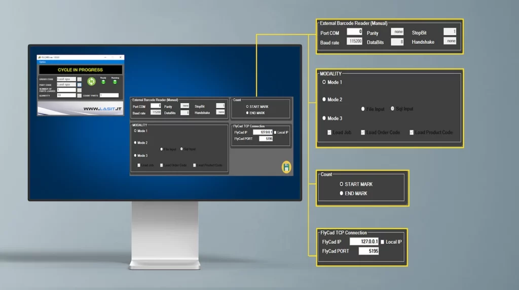
The digitization of manufacturing processes requires that every workstation be able to communicate real-time data to enterprise management systems. The Powermark supports standard industrial communication protocols such as OPC UA, Ethernet/IP, Modbus TCP and Profinet, enabling native integration with Manufacturing Execution System (MES) and ERP.
This connectivity makes it possible to receive marking data directly from the management system, without the need for manual input: the code to be marked, progressive serial number or batch information is automatically transmitted to the laser from the production line. Similarly, the system can send marking confirmations, quality control results, production counters and fault reports to the MES.
Integration with centralized databases ensures complete traceability of the component, uniquely associating each marked part with information such as date and time of manufacture, operator, laser parameters used, and verification result. This is an essential requirement for regulated industries or applications that require compliance certification and traceability throughout the supply chain.
The ability to operate in online mode also enables dynamic management of marking recipes: the system can automatically adjust parameters according to the material, color or surface type detected by the vision system, or select different recipes according to the product code reported by the MES.
Operational efficiency and OEE: how a well-integrated system reduces downtime
Overall Equipment Effectiveness (OEE) is the key indicator for measuring the efficiency of a production line, considering machine availability, performance against rated speed, and quality of parts produced. On well-designed and managed marking lines, OEE values above 98 percent are achievable through optimization of three critical areas: laser system reliability, marking cycle speed, and scrap reduction.
Reliability depends mainly on the stability of the laser source and the robustness of the control electronics. Solid-state sources such as those used in UV and green lasers have operating lives in excess of 30,000 hours and require minimal maintenance. Redundancy of critical systems, such as power supplies and control boards, helps prevent unexpected shutdowns. Real-time monitoring systems can signal anomalies before they result in failures, allowing predictive maintenance and scheduling of interventions in scheduled time windows.
Cycle performance depends on actual marking time and ancillary times such as positioning, verification, and handling. On small electronic components, the marking time for a Data Matrix code can be less than 0.5 second with UV lasers of appropriate power. If the vision system completes acquisition and verification in less than 0.3 seconds and the robot or conveyor takes 0.4 seconds to change parts, the total cycle time is around 1.2 seconds, corresponding to a theoretical throughput of 3000 parts/hour.
Process quality, measured as the percentage of conforming parts, is affected by the repeatability of marking and the effectiveness of in-line control. Systems with self-centering and automatic grading can discard nonconforming parts in real time, preventing marking defects from propagating down the line. This reduces final rejects and improves the OEE quality index, as well as preventing rework or complaints downstream.
Recurring application challenges and solution approaches
Despite technological advances, marking plastic electronic components still presents operational challenges related to material variability, complex geometries and traceability requirements. One of the most common issues is managing contrast on light-colored or transparent plastics. Materials such as natural polycarbonate or white ABS require very precise laser parameters to achieve visible ablation without burning or halos.
The solution is to use UV lasers with very short duration pulses and controlled energy density, possibly combined with pre-treatment or thermal post-treatment additives to enhance contrast. In some cases, the application of a second low-power laser pass can further darken the marked area without compromising the integrity of the material.
Another critical issue involves marking on curved or irregular surfaces, where height variation can lead to loss of focus and reduced quality. Systems with dynamic autofocus or software compensation based on the CAD model of the part enable correct focus to be maintained along the entire profile. Alternatively, the use of extended depth-of-field optics can tolerate height variations up to ±2 mm without significant degradation of marking.
The presence of fillers or additives in polymers can alter laser absorption and generate unpredictable results. Plastics loaded with glass fibers, flame retardants or metallic pigments require accurate process testing and may need periodic parameter adjustments depending on material batches. Recording optimal parameters for each material-color combination and managing recipe libraries in the control software facilitate reproducibility and reduce setup times.
Regulatory compliance and industry standards
The marking of electronic components must meet specific regulatory requirements to ensure readability over time, resistance to external agents and compliance with traceability standards. ISO/IEC 16022 defines the technical specifications for Data Matrix codes, which are the de facto standard for marking components in small spaces. Minimum module size, quiet margin, and error correction must be met to ensure reliable decoding even under harsh operating conditions.
ISO/IEC 15415 establishes criteria for evaluating symbol quality, including parameters such as symbol contrast, modulation uniformity, axis defects and decoding. For automotive or aerospace applications, minimum grading of B or better may be required, verifiable only through certified vision systems.
In electronics, compliance with the RoHS directive requires that the materials used for marking contain no hazardous substances. Laser marking, being a process of ablation or surface modification without addition of material, is inherently compliant with this directive. However, it is important to verify that any preliminary surface treatments or additives applied to enhance contrast comply with the required limits.
Final Conclusions.
UV and green laser marking on plastic electronic components represents a mature but evolving technology in which the quality of the end result depends on the harmonious integration of laser source, optics, vision system and control software. The choice between UV and green must be based on objective technical evaluations related to the material, contrast required and production cadence, avoiding generalizations or standardized approaches.
In-line integration and connectivity with enterprise management systems transform the laser marker from a production tool to an intelligent node in the digital factory, capable of acquiring data, verifying quality, and communicating with MES and ERP in real time. Solutions such as the Powermark, with modular architecture, centralized control and integrated vision, meet the needs of manufacturers seeking operational efficiency, flexibility and scalability in high-volume environments. The ability to achieve OEE values above 98 percent through system reliability, cycle optimization, and in-line quality control represents a significant benchmark for the industry, demonstrating that laser marking can not only be a quality process, but also a factor in industrial competitiveness.