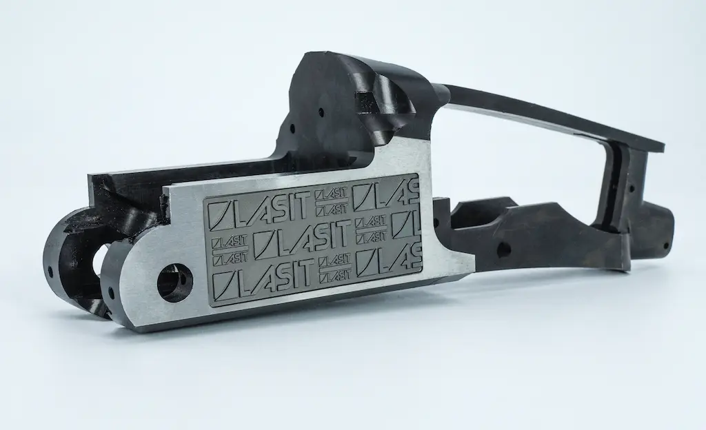
In the aerospace, defense and firearms sectors, permanent traceability of components is not an optional extra, but a mandatory regulatory requirement. However, anyone who has worked with components subjected to aggressive surface treatments is familiar with the problem: a standard laser marking, no matter how well executed, can disappear or become illegible after sandblasting, application of protective coatings such as Cerakote, or re-burnishing processes. When it comes to lower and upper receivers for military applications, certified aerospace components or parts subject to MIL-STD-130 regulations, this is not acceptable.
The challenge is not simply to mark deeper. There is a need to develop a structured approach that combines controlled engraving depth, surface quality of the engraved background, and sufficient optical contrast to ensure readability of DataMatrix codes or alphanumeric serials even after tens of microns of surface material have been removed. This is exactly what multi-level deep engraving aims to solve.
The problem of surface marking in severe industrial settings
Conventional laser marking on steel or aluminum typically reaches depths between 20 and 50 micrometers. This is more than sufficient for standard applications, where the component does not undergo particularly aggressive post-marking treatments. But when that component needs to be sandblasted to remove machining slag, coated with high-strength ceramic coatings, or subjected to chemical surface finishing processes, those 20 to 50 micrometers can be completely removed or altered to the point where code readability is compromised.
The problem becomes even more critical when we consider operational wear and tear. A component intended to operate in military theater, exposed to extreme environmental conditions, may experience mechanical abrasion, corrosion, and contact with chemicals. Marking that is too superficial simply does not survive the life cycle of the component. And in contexts where traceability is tied to safety, preventive maintenance, or management of critical components according to standards such as ASTM F3001 or MIL-STD-130, losing the legibility of a UDI code or serial is not just a technical inconvenience: it is a regulatory violation.
The multi-level approach: building depth with control
The solution is not simply to increase the laser power and hope that the material will be removed deeper. Engraving performed with poorly calibrated parameters can create excessive Heat Affected Zones (HAZs), microfractures at the bottom of the engraving, or rough edges that compromise code readability even if the nominal depth is sufficient. The multi-level approach structures the process in successive steps, each with specific parametric objectives.
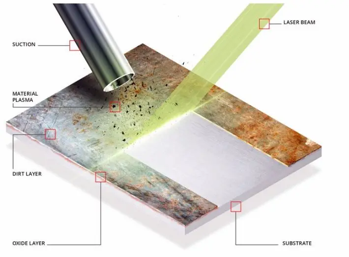
The first level has a preparatory function. On components that arrive at the marking station with surface oxidation, residues from previous machining, or substrate inhomogeneity, a first pass at medium parameters allows the surface to be uniform. This pre-marking cleaning is not always necessary, but on steels that have already been heat-treated or on aluminums that have undergone machining, it can make the difference between a homogeneous marking and a marking with zones of varying quality.
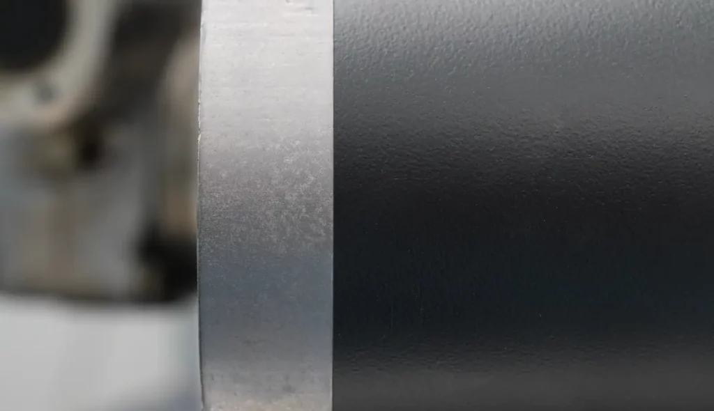
The second level is the heart of the process: the actual deep engraving. This is where the critical parameters come into play that determine how much material is actually removed and with what quality. The frequency of the laser is lowered from a standard marking, typically in the 20-80 kHz range, because lower frequencies mean higher energy per single pulse and therefore higher ablation capacity. The scanning speed is reduced, often down to 100-400 mm/s, to allow more interaction between the laser beam and the material. The overlap, i.e., the overlap between successive laser traces, is increased to 60-85% to ensure that the engraving background is uniform and has no ridges or irregularities that could compromise the optical reading of the code.
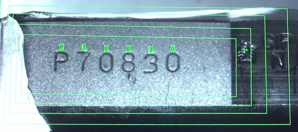
The third layer, not always necessary but useful in many applications, has a contrast enhancement function. A final pass at different parameters, often using an approach similar to annealing (controlled oxidation marking that creates color contrast without material removal), can significantly improve the visual contrast between the etched background and the surrounding material. This is particularly useful when the marking must be read not only by machine vision systems but also by operators in less than optimal lighting conditions.
The decisive role of MOPA technology
Fiber lasers with master oscillator power amplifier (MOPA) technology offer a decisive advantage in this type of application. Unlike standard fiber lasers, where the pulse duration is fixed, a MOPA allows the pulse length to be modulated over a very wide range, typically from 4 to 200 nanoseconds. This flexibility results in much finer control over the energy balance of the process.
When working with longer pulses, in the range of 50-200 nanoseconds, more thermal energy is transferred to the material. This increases the material removal capacity per single pulse, making the deep engraving process more efficient. At the same time, control over pulse duration allows minimizing the thermally altered zone, reducing the risk of microfractures or unwanted metallurgical alterations at the bottom of the engraving. On high-strength steels such as 4140 or 4150, commonly used for firearms receivers, this control is essential to achieve deep engraving without compromising the structural integrity of the component.
Average laser power is obviously an important factor, but it is not the only determining parameter. For deep engraving applications on medium-sized components, powers in the range of 30-50W are generally sufficient. In contexts where productivity is critical and volumes are high, one can go up to 100W, but the increase in power must always be accompanied by a reoptimization of the other parameters to avoid undesirable thermal effects.
Target depth and quality verification
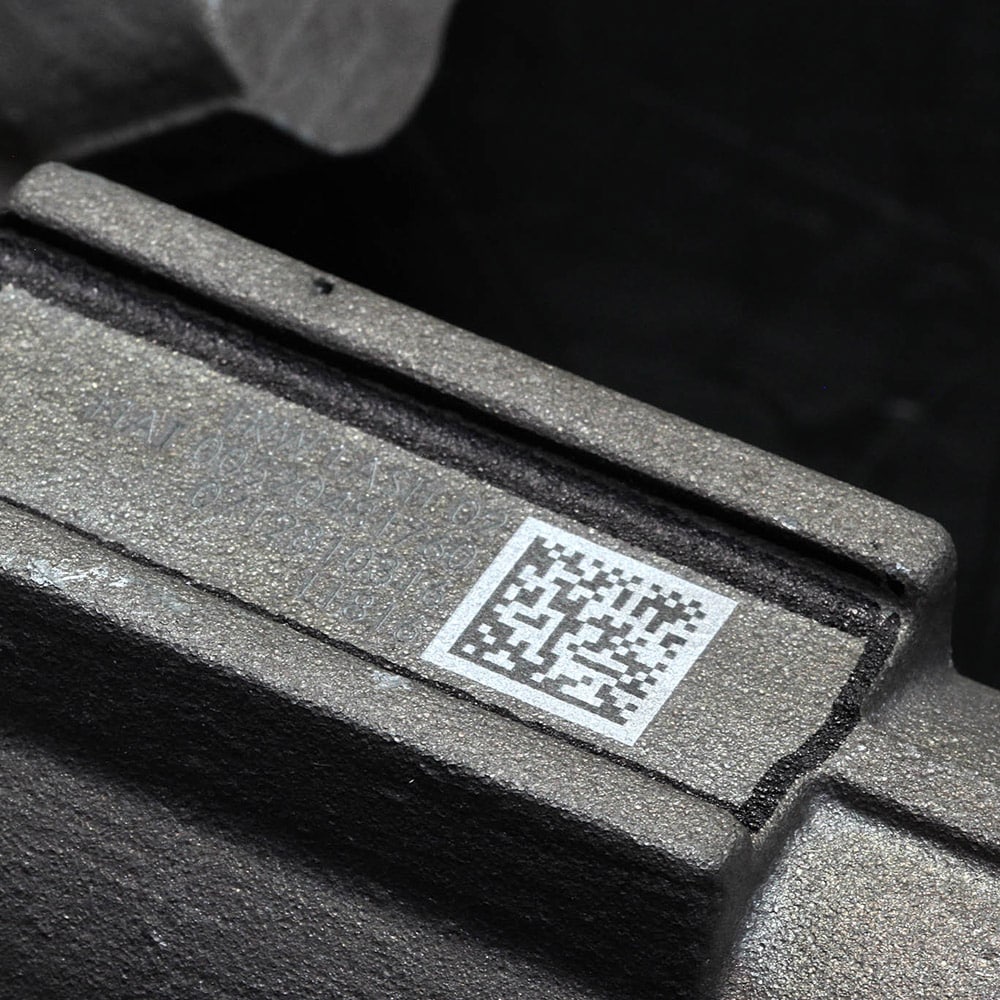
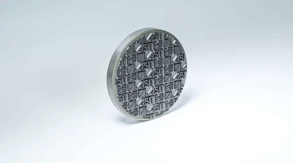
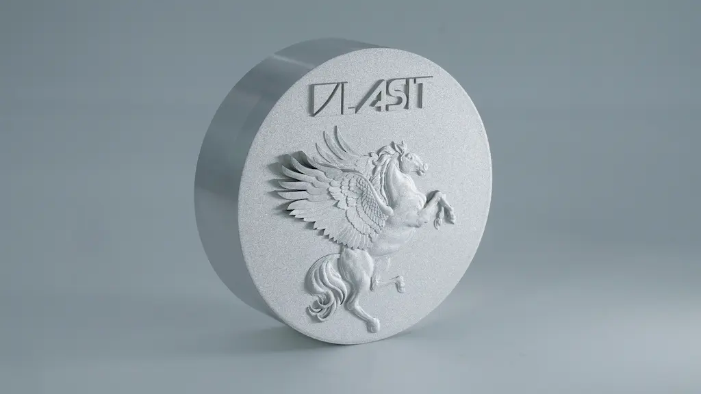
When we talk about deep engraving for components that will undergo post-marking treatments, the typical target depth is in the 150-300 micrometer range. This safety margin ensures that, even after aggressive sandblasting that removes 50-80 micrometers of surface material or after the application of coatings that may partially mask the engraving, the code remains perfectly legible. In some cases, for particularly critical components or those destined for very long life cycles, greater depths of up to 500 micrometers can be achieved, but at this point it becomes essential to verify that the etching does not compromise the mechanical strength of the section.
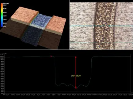
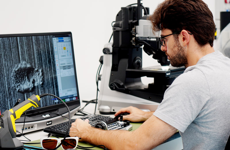
Depth verification cannot be visual or approximate. Instruments such as roughness meters, profilometers, or 3-D microscopes are essential to accurately measure the true depth of the engraving and verify that the bottom is sufficiently uniform. An engraving that is deep but has an uneven bottom may have lower grading than one that is less deep but performed with optimal parameters.
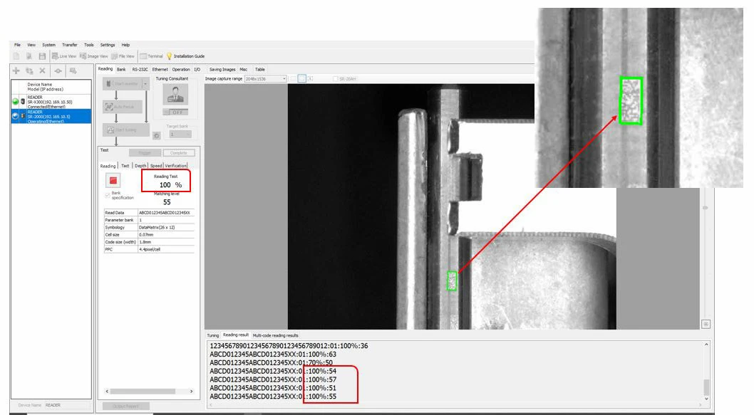
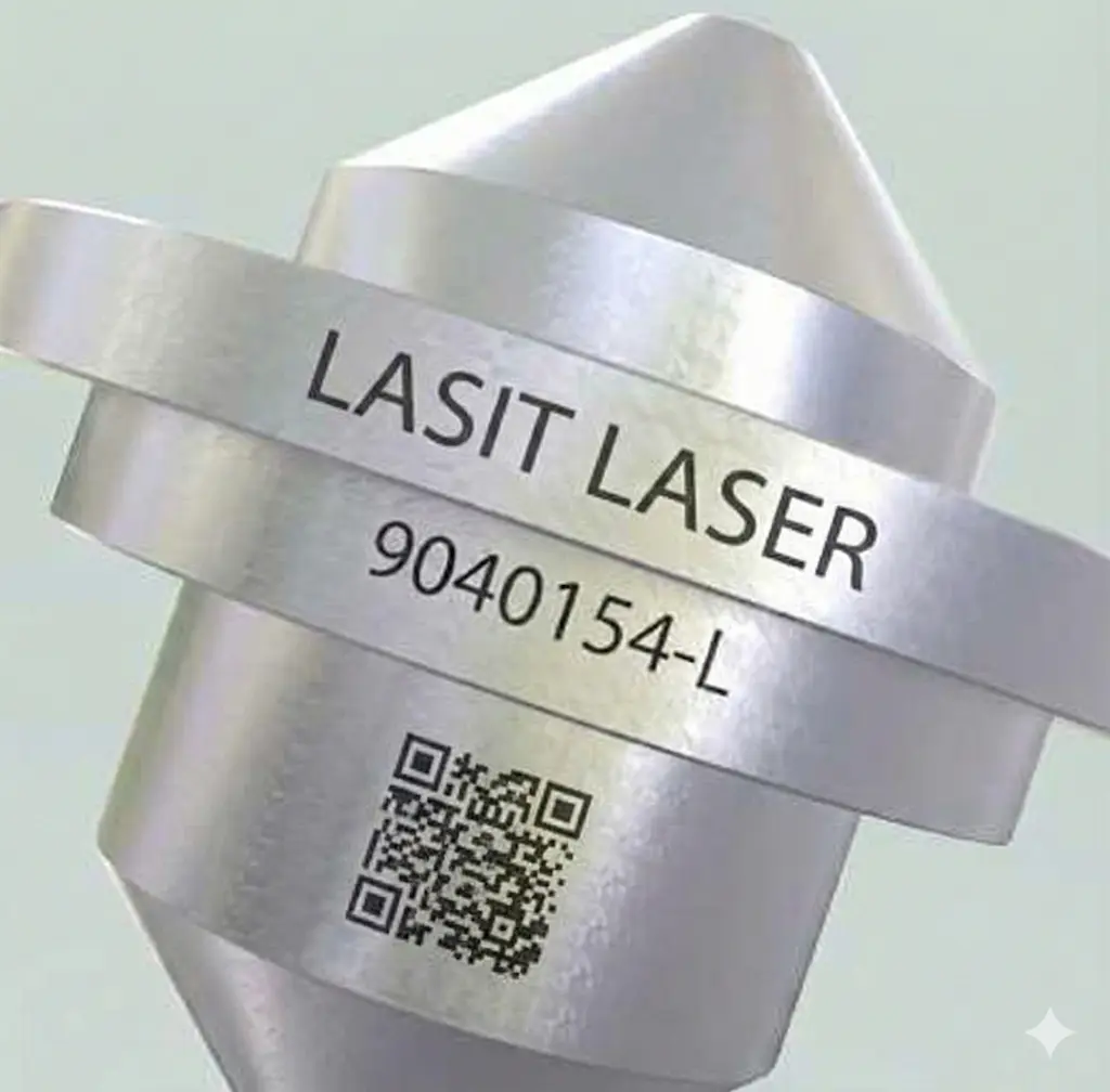
DataMatrix or QR code grading is evaluated according to the ISO/IEC 15415 standard, which assigns a grade from A (excellent) to F (unreadable). For aerospace and defense applications, the goal is to maintain A or B grading even after surface treatments. This requires not only adequate depth, but also sufficient optical contrast and an absence of defects such as missing pixels or geometric code deformations.
Multi-pass incremental approach: control vs. speed
One of the most important design choices when defining a deep engraving process concerns the number of passes. One might think that performing the engraving in a single ultra-aggressive pass would be more efficient, but experience shows that an incremental approach with 3-10 successive passes offers qualitatively superior results.
Each pass removes a relatively thin layer of material, on the order of 30-50 micrometers. This allows better control over the geometry of the etched bottom, limits localized thermal stresses, and allows parametric intervention between passes if problems are observed. In addition, the multi-pass approach reduces the risk of burr formation or accumulation of molten material on the edges of the etch, typical issues when trying to remove too much material in a single pass.
The cost in terms of cycle time is obviously higher than for a standard surface marking, but for high value-added components such as aerospace or military firearms, where the cost of the component itself is in the hundreds or thousands, the increase in cycle time (typically from a few seconds to 15-30 seconds for a standard size DataMatrix) is perfectly acceptable.
Materials and application specifics
The most common materials for this type of application have different characteristics that influence the parametric choice. High-strength alloy steels, such as 4140 and 4150 used for receiver, require relatively high energies for ablation but offer good uniformity of response. Aerospace aluminum, typically 7075-T6 or 6061-T6, is softer and therefore easier to deep etch, but tends to generate burrs and requires optimized parameters to avoid melt buildup. Titanium Ti-6Al-4V, which is increasingly used in aerospace applications because of its excellent strength-to-weight ratio, is probably the most challenging material: it requires high energies, tends to reflect a significant portion of laser radiation, and can develop extensive HAZs if parameters are not perfectly calibrated.
For each of these materials, the parametric starting point is different, and optimization requires systematic testing. A laboratory equipped with multiple laser sources and advanced measurement instrumentation (profilometers, 3-D microscopes, grading systems) makes it possible to develop reliable and replicable parametric sets in production.
From sampling to production: process transfer
Developing optimal parameters in the laboratory is only half the job. The transition from sampling to production requires that the process be robust with respect to unavoidable variabilities: dimensional tolerances of components, lot-to-lot variations in material, progressive wear of the laser source. A well-designed deep engraving process must include sufficient parametric safety margins to ensure that, even in the presence of these variabilities, the end result remains within specifications.

This means defining not only nominal parameters but also acceptable ranges, implementing in-process controls (e.g., spot grading checks during production), and providing preventive maintenance procedures to ensure that the laser source maintains performance over time. MOPA fiber lasers with expected lifetimes in excess of 100,000 hours offer a significant advantage in this regard in terms of stability and reduced maintenance costs.
Regulatory compliance and documentation
For aerospace and defense components, traceability does not stop at physical marking. Every marking process must be documented, validated, and comply with applicable standards. MIL-STD-130 defines requirements for permanent marking of components destined for the U.S. Department of Defense, specifying not only the technical characteristics of the marking but also supplier qualification processes and verification procedures. ASTM F3001, on the other hand, applies to medical devices and requires that the UDI marking withstand sterilization and use cycles without loss of legibility. SAE AS9132 defines quality standards for aerospace marking.
A laser marking system supplier working in these areas must be able not only to supply the hardware and process parameters, but also to support the customer in the documentation required for process qualification, the establishment of quality control procedures, and the management of nonconformities.