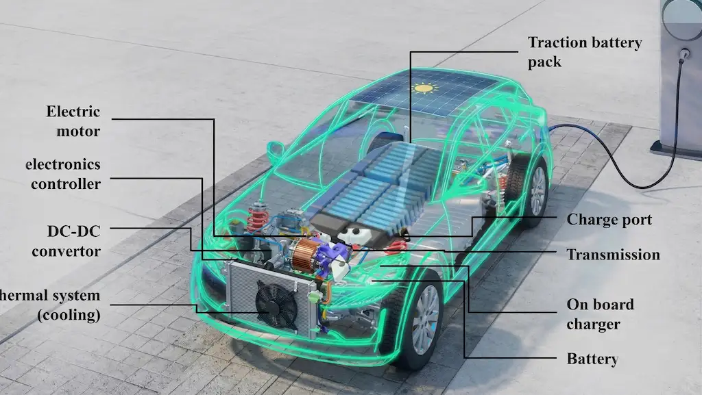
The transition to electric mobility has reshaped automotive manufacturing priorities. Behind every battery pack-whether it is 60 kWh for an urban hatchback or over 100 kWh for a long-range SUV-there are thousands of components that must be uniquely identified, traced along the entire value chain, and remain legible for decades. A 4680-size cylindrical cell, a copper busbar for distributing bounty currents, a stator for a permanent magnet motor: each of these elements carries marking requirements that traditional technologies struggle to meet.
The problem is not just operational. Regulations such as UL 2580 for batteries from electric vehicles, UNECE Regulation R100 for the safety of storage systems, and increasing pressures for compliance with the EU’s battery passport supply chain impose fine-grained traceability starting with the elemental component. Against this backdrop, permanent laser marking has emerged as the technology standard of choice-not as a matter of trend, but for very specific physical, economic, and regulatory reasons.
Why traceability of EV components is a non-negotiable requirement
A modern electric vehicle contains between 2,000 and 8,000 electrochemical cells, depending on the chemistry and format adopted (NMC, LFP, NCA; cylindrical, prismatic, pouch). Each cell is a safety-critical component: an untraceable manufacturing defect can result in uncontrolled thermal events during operation or charging. Capillary traceability makes it possible to circumscribe defective batches, perform surgical recall campaigns, and provide regulatory authorities with the required documentation in the event of an accident.
At the regulatory level, Battery Regulation (EU) 2023/1542 requires that by 2027 every EV battery with a capacity greater than 2 kWh have a digital passport with information traceable down to the module level, and tending to the individual cell. In parallel, OEMs operating under IATF 16949 quality systems must demonstrate full traceability of safety-critical components-a category that includes cells, busbars and stators without exception. The absence of legible marking at the field stage amounts to a break in the traceability chain, with direct consequences for the manufacturer’s legal liability.
The limitations of traditional marking technologies in EV production.
Before laser marking became accessible on an industrial scale, EV component manufacturers mainly used three approaches: adhesive labels, pad printing, and, for robust metal components, cold punching. Each of these presents specific critical issues in the environment of a battery assembly plant.
Adhesive labels remain the most popular solution in manual or semi-automatic processes, but their fate in a battery pack is problematic. The thermal cycling of a battery pack in use-with fluctuations between -30 °C and +60 °C within each charge-discharge cycle- rapidly degrades adhesives. This is compounded by exposure to the electrolyte, which in the case of microleaks can impair code readability in a matter of months. In high-volume plants, the pace of label application is often a bottleneck: each operation requires a cycle time of between 2 and 5 seconds per component, incompatible with lines operating at 1,200 or more cells per hour.
Cold-punching, while providing absolute permanence, imposes mechanical deformation on the component that is incompatible with the thin geometries of cylindrical 21700 or 4680 cells (wall thickness 0.2-0.4 mm) and with copper busbar components, which are subject to micro-cracking that alters conductive properties. Finally, pad printing introduces inks that can interfere with downstream chemical processes-particularly laser soldering of terminals and adhesive bonding of cells into the module.
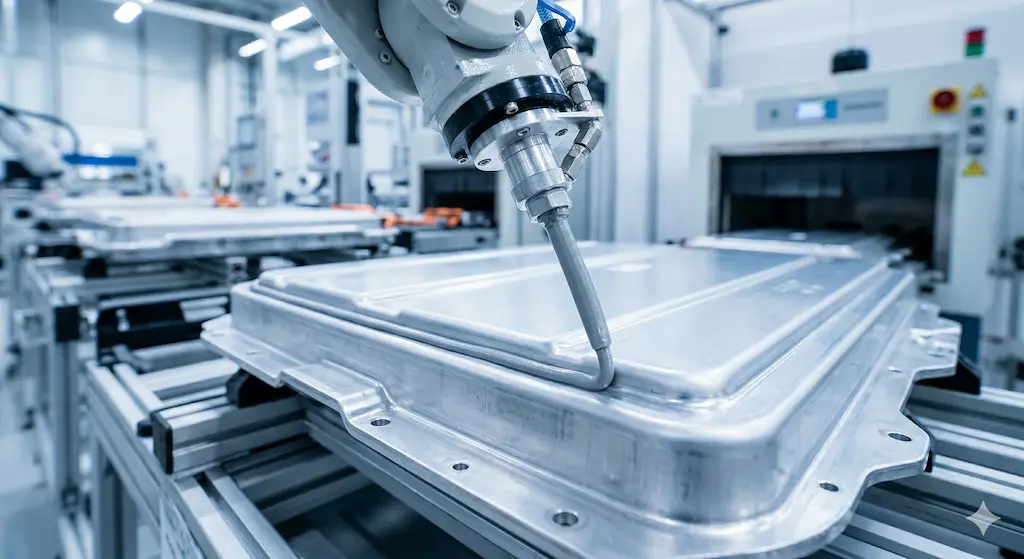
How permanent laser marking on EV battery components works
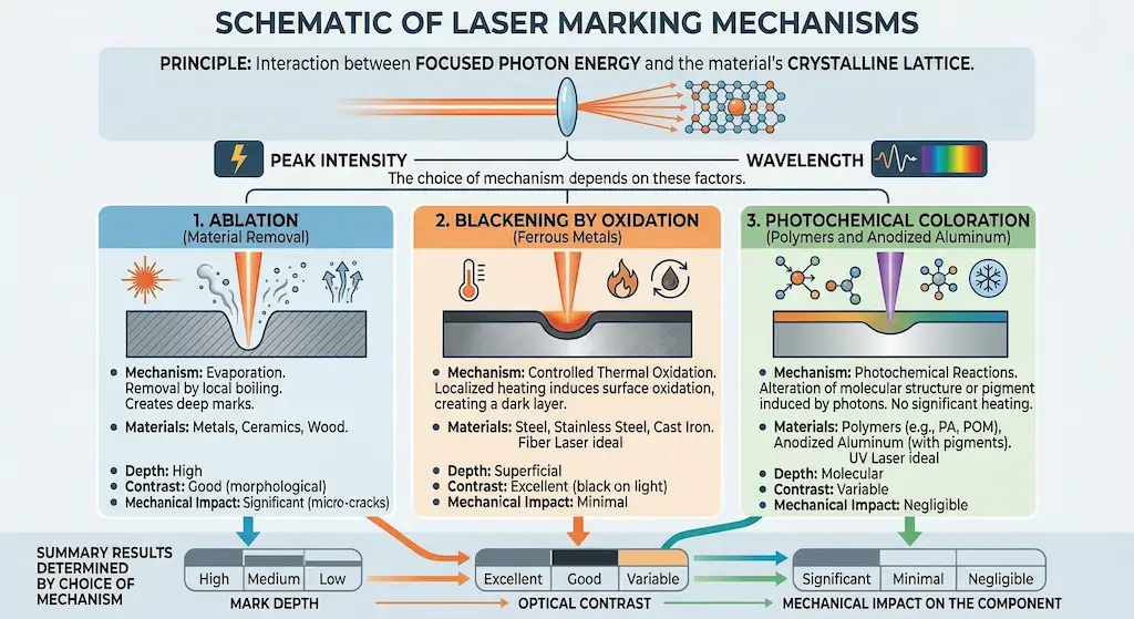
Laser marking exploits the principle of interaction between focused photon energy and the crystalline lattice of the material. Depending on peak intensity and wavelength, the beam can induce three types of surface modification: ablation (removal of material by evaporation), blackening by oxidation (typical of ferrous metals with fiber lasers), and photochemical staining (characteristic of UV lasers on polymers and anodized aluminum). The choice of mechanism determines the depth of the mark, the optical contrast achievable, and the mechanical impact on the component.
For cylindrical cells made of stainless steel or nickel, 20-50 W fiber lasers with 1064 nm wavelengths typically operate in the blackening regime at scan rates between 800 and 2,000 mm/s, producing 2D DataMatrix with a minimum modulus of 0.3 mm and sufficient contrast for readout at 400 mm distance. On pouch-format cells with laminated aluminum casing, the process window narrows significantly: aluminum has high reflectivity at 1064 nm, making 532 nm (green) or 355 nm (UV) sources preferable, capable of absorbing up to 40 percent more energy on the same substrate and operating with 20-35 μm spots without risk of perforation.
Operating parameters for cells, busbars and stators: typical configurations
The diversity of materials and geometries means that a single laser configuration does not cover the full range of EV components. Proper parameterization is the determining factor between a brand with OCV (Overall Cell Verification) contrast above 90% and a degraded area that causes scrap and rework.
| Marking parameters for major EV components. | |
| Cylindrical cell 21700/4680 (steel) | Fiber laser 30 W, 1064 nm – speed 1,200 mm/s, frequency 80 kHz, spot 50 μm, 2 passes |
| Cell pouch (laminated aluminum) | UV laser 5 W, 355 nm – speed 400 mm/s, frequency 40 kHz, spot 25 μm, 1 pass |
| Copper busbar (2-8 mm thick) | Green laser 20 W, 532 nm – speed 600 mm/s, frequency 60 kHz, defocus +0.3 mm |
| Aluminum busbar (1-4 mm thick) | Fiber laser 20 W, 1064 nm – blackening mode, speed 900 mm/s, frequency 100 kHz |
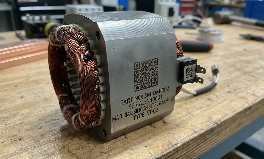
| Stator (Fe-Si plate pack, Cu windings) | Fiber laser 50 W, marking on annular corona – speed 1,500 mm/s, power 70%. |
| Minimum acceptable contrast (Grade A) | AIM DPM Quality Guideline ≥ 0.6 contrast ANSI B grade |
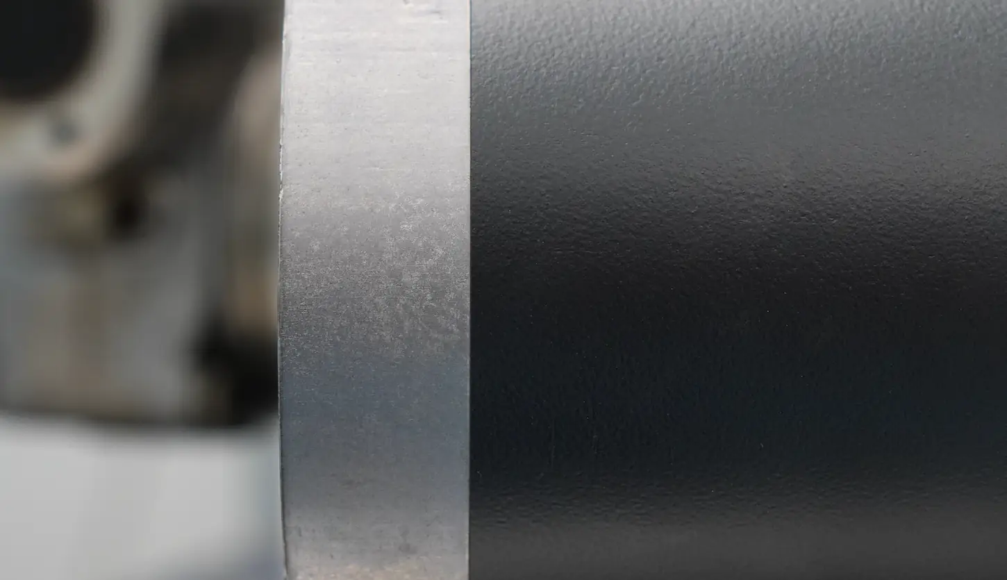
Copper busbars deserve specific note: copper reflects more than 95 percent of the radiation at 1064 nm at room temperature, making it virtually impossible to mark with standard fiber lasers without risk of optical damage to the system. Transitioning to green sources at 532 nm, with copper’s absorbance about 4 times higher, solves this problem but requires dedicated optics and more careful thermal management to avoid micro-cracking on the conductive surface, which is critical for solder joint contact resistance.
Laser cleaning pre-soldering and pre-bonding: operational synergies in module production
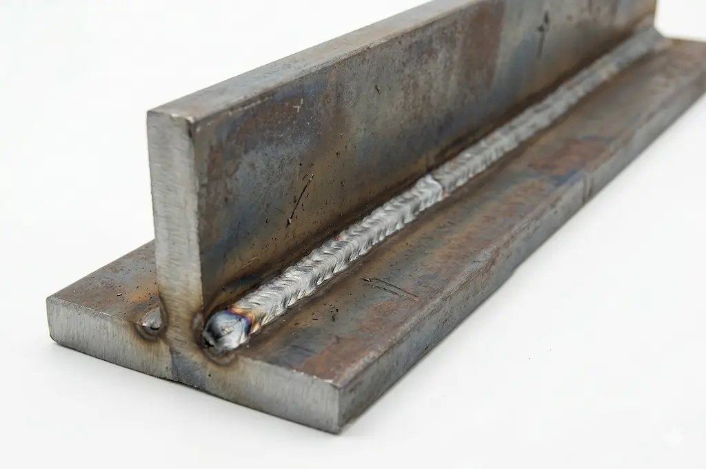
An aspect often underestimated in EV process planning concerns the surface preparation that precedes the operations of laser welding of the terminals and structural bonding of the cells into the module. The presence of native oxides on the aluminum, organic films on the copper, or lamination residues on the cell envelope compromises the quality of the solder joint and the adhesion of structural adhesives, resulting in mechanical strength and in-cycle terminca problems.
Laser cleaning-or selective photothermal decontamination-exploits the same physical principles as marking, but with opposite objectives: instead of modifying the surface functionally, it returns it to a controlled state of optimal cleanliness and roughness. With enlarged spot (100-500 μm) and repetition frequency in the range of 20-50 kHz, a pulsed beam at 1064 nm removes oxide layers 0.5-5 μm thick without altering the metallurgy of the substrate. The result is verifiable inline by measurement of contact angle: properly treated surfaces show angles of less than 10° on aluminum (versus 30-60° for untreated material), ensuring adhesion of two-component epoxy adhesives in excess of 18 MPa in tension.
The industrial opportunity is obvious: integrating cleaning, marking, and optical verification operations in a single station-or at consecutive locations on the same line-eliminates intermediate handling, reduces WIP, and allows code to be read right after cleaning, before any post-process contamination compromises readability. In our experience with customers in the battery module industry, this architecture has enabled reductions in total process cycle time of up to 30 percent compared to compartmentalized solutions.
Laser marking versus alternatives: when to choose which technology
Comparisons between laser marking and alternative technologies cannot ignore the specific operating environment. RFID tags offer superior information content and do not require line-of-sight to read, but the cost per unit (€0.05-0.50 per tag in scaled volumes) over productions of hundreds of millions of cells represents a unit cost burden that no OEM EV can ignore. In addition, RFID tags in the vicinity of significant metal masses-exactly the condition of a battery pack-undergo antenna detuning resulting in reduced read reliability.
Industrial inkjet (CIJ or DOD) is competitive in terms of initial investment, but it introduces inks that must be compatible with all downstream process fluids: electrolytes, cleaning solvents, and adhesive solvents. Chemical compatibility validation is a long and often iterative journey, particularly in a rapidly evolving industry such as battery chemistry. When faced with a change of electrolyte or a new bonding process, inkjet marking requires a new qualification campaign.
Laser marking, by contrast, is inherently chemically inert after the process: it does not introduce foreign material to the surface, is resistant to all solvents and chemicals typical of battery environments, and does not degrade over time at temperature. The cost per brand, once the system is amortized, is measured in fractions of a cent; on volumes of 500,000 cells/year, the differential from adhesive labels pays back the investment over a typical 18-36 month horizon. Systems such as LASIT’s Powermark-designed specifically for electronic and small components with interchangeable UV, green and fiber sources-demonstrate that a single platform can cover the full range of substrates found in a battery assembly plant.
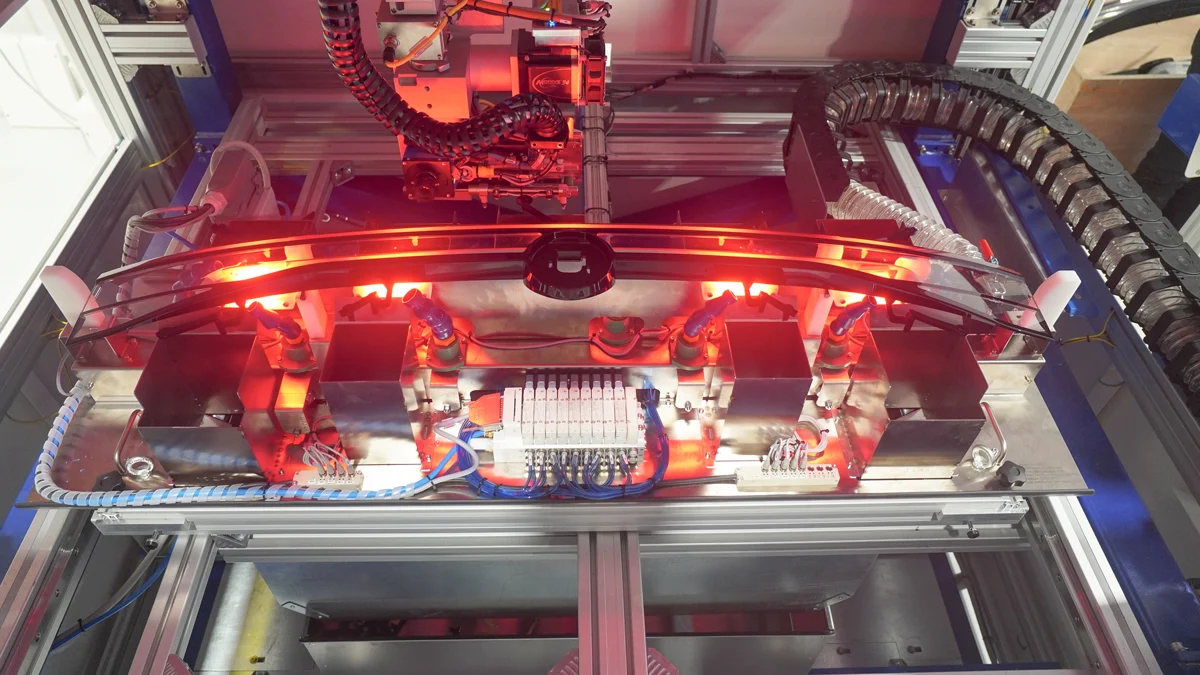
Production line integration: how to deploy laser tracking in an EV plant
The choice of laser system is only the first step. Integration into an EV production line-which can operate at rates exceeding 1,200 units/hour for cells-requires careful design of the station architecture. Beam scanning direction, ablation fume management, vision system for code verification, and interface with the factory MES all determine the quality of the deployment.
On the hardware side, fly-on-the-fly systems (marking on a moving component on a belt) enable the elimination of dedicated idle stations, reducing the footprint and aligning the marking cycle time with the line cadence. With scanning speeds up to 10 m/s and integrated position encoders, it is possible to mark DataMatrix with 32×32 modules on cells moving at 0.5 m/s without loss of quality. For busbars, which require more precise positioning, stations with dedicated handling and verification system with 5 MP camera and coaxial lighting are preferred to ensure Grade A according to AIM DPM on every part.
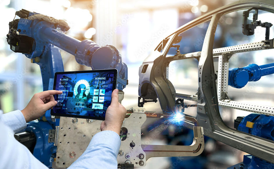
On the software side, integration with OPC-UA and MQTT protocols enables bidirectional communication with the MES/ERP layer: the marking system receives the data to be encoded (serial numbers, production batch, timestamps, process parameters) and returns the result of the optical verification in real time, feeding the digital twin of the component. This architecture is the operational basis for complying with the traceability requirements of the EU Battery Regulation within the deadlines.
Conclusions
Laser marking is not simply a more modern alternative to traditional solutions: in the production of electric vehicle components it is, increasingly, the only technology that can simultaneously meet the requirements of permanence, chemical inertness, cycle speed and regulatory compliance. In-depth knowledge of the process parameters for each substrate-steel or aluminum cells, copper or aluminum busbars, Fe-Si sheet metal stators-is the differential between a system that produces readable brand and one that generates expensive scrap. Synergistic integration with laser cleaning pre-welding and pre-bonding adds further operational value, consolidating multiple processes into a single station architecture. For those designing today’s battery assembly lines of the next decade, correctly defining the laser traceability strategy is an investment with measurable returns-in quality, compliance, and unit cost.