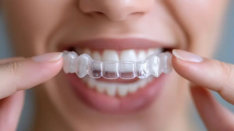
The global market for clear aligners has been growing at an average annual rate of more than 18 percent over the past five years, with projections estimating a volume of more than $14 billion by 2030. Behind this expansion lies a manufacturing challenge that production managers are well aware of: each aligner is a custom-made medical device intended for a specific patient and a specific phase of treatment, making individual traceability not an option, but a compliance requirement.
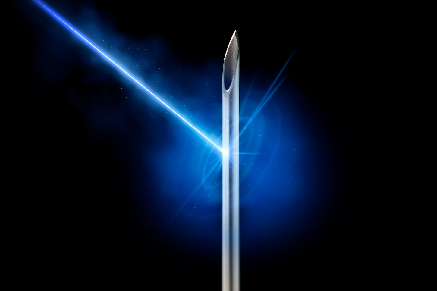
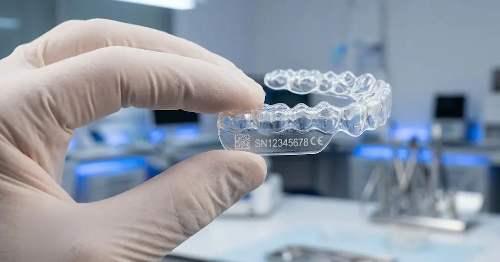
MDR 2017/745 regulations in Europe and FDA’s 21 CFR Part 820 in the United States require Class II medical device manufacturers to adopt verifiable Unique Device Identification (UDI) systems throughout the supply chain. Applying an identification code to a thin, transparent, curvilinear, thermosensitive component such as a PETG or thermoplastic polyurethane aligner rules out a priori contact marking technologies and inkjet systems subject to uncertain adhesion and durability. The UV laser, with its ability to induce localized chemical changes without generating macroscopic heat, is now the most reliable technological answer to this need.
Why UV lasers are ideal for clear aligners
The choice of UV laser-typically at 355 nm wavelength-for marking transparent aligners is not arbitrary: it derives from a combination of optical, photochemical, and thermal properties that no other laser source offers comparably on this specific substrate.
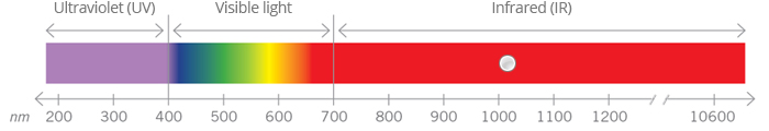
The first reason is photon selective absorption. Transparent thermoplastic polymers absorb UV radiation much more efficiently than near-infrared (1064 nm of Nd:YAG or fiber lasers) or green (532 nm). This higher absorbance allows sufficient energy to be deposited to trigger photodegradation of the polymer chains in a surface layer only a few micrometers deep, without the residual radiation propagating through the thickness of the material causing internal structural damage.
The second reason is the very small heat input. The dominant mechanism in the UV laser is photochemical, not photothermal: high-energy photons directly break chemical bonds (cold ablation) instead of converting to heat. The practical result is that the thermally altered zone (HAZ) remains less than 5 μm, eliminating the formation of micro-fractures, local deformations, or extensive color changes that would compromise both the orthoptic function of the aligner and its aesthetic acceptability by the patient.
The third factor is the size of the focused spot. UV 355 nm systems operate with spots between 20 and 50 μm in diameter, which results in sufficient marking resolution for Data Matrix codes of 2×2 mm size with 100 μm cells, which can be read by standard industrial scanners with more than 99.5 percent reliability. This resolution is unattainable by fiber laser systems operating at 1064 nm, whose typical minimum spot is around 25-30 μm but with thermal effects incompatible with thin polymers.
Engineering challenges: between transparency, geometry and thermal fragility
Anyone who has attempted to adapt a standard laser marking system to the production of aligners has encountered a number of critical issues that emerge not from the technical specifications of the laser, but from the interaction between beam and material under real production conditions.
The risk of micro-fractures and the process window
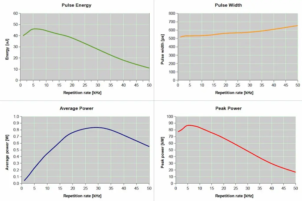
PETG and TPU used in the production of aligners have a glass transition temperature (Tg) between 65 and 85°C. Even limited heat input can generate localized temperature gradients sufficient to trigger micro-stress in the polymeric lattice. In applications where the part is then thermoformed or subjected to sterilization cycles, these micro-fractures propagate and can compromise the mechanical integrity of the aligner. The acceptable process window is therefore narrow: peak fluence typically between 0.5 and 2 J/cm², repetition frequency of 20 to 80 kHz, and scanning speed between 500 and 2000 mm/s depending on material thickness.
Maintaining transparency and secondary marks
A frequent mistake in setup is the tendency to set parameters too aggressively to achieve visible contrast. On transparent materials, UV laser marking produces contrast through a localized change in refractive index and surface micro-opacification, not through carbonization as on dark polymers. If fluence exceeds the critical threshold, so-called secondary marks are formed: halos of diffuse opacity around the marked area that alter the overall transparency of the device, reducing aesthetic acceptability and potentially generating nonconformity in quality control.
The complexity of fixing on three-dimensional geometries
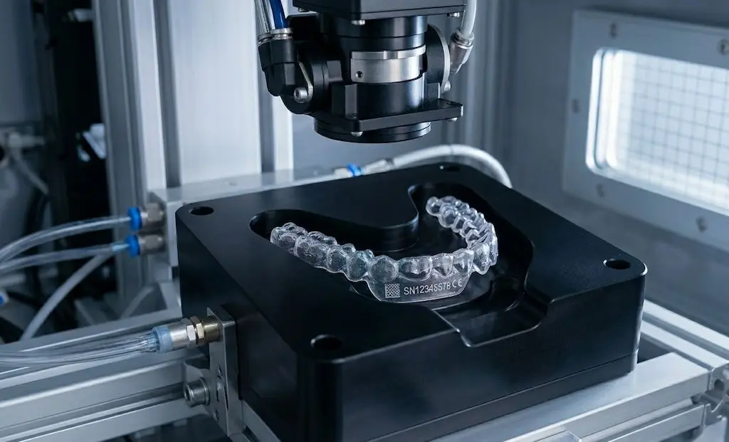
An aligner is not planar: it is a three-dimensional structure with surfaces of variable curvature, non-uniform thicknesses (0.4-1.5 mm depending on the stage of treatment) and geometries dependent on the anatomy of the individual patient. The depth of field of a focused UV system is typically ±0.2 mm: outside this range, the spot size increases and the energy density falls below the marking threshold. The design of positioning templates therefore becomes as critical as the selection of laser parameters, requiring custom fixtures or autofocus systems with feedback on the signal.
The implementation process: from qualification to production
Bringing UV marking of aligners into production is not a plug-and-play activity. It requires a structured process that goes through at least six distinct steps, each with precise documented deliverables for MDR/FDA compliance purposes.
| 1.Define marking requirements Identify the required UDI code (GS1, HIBCC or ICCBBA), reading level (DL, PI), available application surface, post-sterilization and post-use readability requirements. Define variable content (patient ID, lot, treatment step) and static content (manufacturer code). |
| 2.Specific material testing Run a DOE (Design of Experiments) matrix by varying fluence, repetition rate, scan speed and number of passes. Evaluate contrast, HAZ, absence of secondary marks, post-thermoforming hold, and readability with ISO/IEC 15415 and 15416 compliant scanner. The minimum threshold of acceptability is typically Grade B (ISO/IEC 15415) for industrial scanners, Grade C for internal traceability. |
| 3.Develop and lock parameters Crystallize optimal parameters in a versioned system recipe. Document process tolerances (+/-10% on fluence, +/-5% on velocity) and alarm limits. The recipe should include focus parameters as a function of aligner geometry. |
| 4.Design of positioning jigs Design specific fixtures for each type of aligner (upper/lower, step 1-40+). The fixtures should ensure repeatable positioning with tolerance ≤ 0.1 mm on XY position and ≤ 0.05 mm on Z dimension (depth of field). Typical materials: anodized aluminum or PEEK for resistance to UV-C or plasma cleaning. |
| 5.Integration of patient/batch data Connect the laser system to the orthodontist’s MES or order management system for automatic populating of variable fields. The standard exchange format is XML or HL7 FHIR for integrations with clinical software. Implement a pre-marking verification mechanism (reading the generated code before release) with automatic reject in case of mismatch. |
| 6.IQ/OQ/PQ Validation Perform the triple validation required by 21 CFR Part 820 and ISO 13485: Installation Qualification (verification of installation), Operational Qualification (verification of operation |
| Typical operating parameters – UV marking transparent aligners | |
| Laser wavelength | 355 nm (UV DPSS or UV fiber) |
| Average working power | 0.5 – 3 W (material-dependent) |
| Frequency of repetition | 20 – 80 kHz |
| Scanning speed | 500 to 2,000 mm/s |
| Focused spot size | 20 – 50 μm |
| Depth of Field (DoF) | ± 0.2 mm |
| HAZ typical | < 5 μm |
| Typical code | Data Matrix 2×2 mm, 100 μm cell |
| Target readability (ISO 15415) | ≥ Grade B |
| Cycle time per marking | < 2 s for single aligner |
Automation and inline integration: from closed cell to one-piece flow
The real challenge for large aligner manufacturers-which handle volumes in the hundreds of thousands of units per month-is not marking the individual aligner, but integrating the process into a high-cadence production line with consistent quality and zero rework.
Closed island marking cells
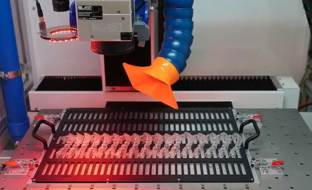
The most common configuration for medium to high production is the closed-island laser cell: a compact system with galvanometer scanner, integrated UV source, fume extraction system, and automatic or semi-automatic aligner fixing unit. The operator inserts a tray of ordered aligners (typically 8-24 pieces per tray), the cell recognizes the layout via a 2D vision system, marks each aligner in the designated position, and releases the tray. Typical throughput is 600-1,200 aligners/hour with a nonconformance rate of less than 0.1 percent on optimized systems.
One-piece flow integration in thermoforming line
For more advanced installations, UV marking is integrated directly into the thermoforming line: the aligner is marked immediately after trimming, still constrained to the positioning stand, before packaging. This approach eliminates a dedicated handling station, reduces WIP (Work in Process) and ensures that each aligner is traceable from the moment of production completion. The main challenge is to synchronize the marking cycle time (< 2 s) with the cadence of the thermoforming machine, which can vary between 8 and 30 s per part depending on the model.
Quality control with vision and OCR
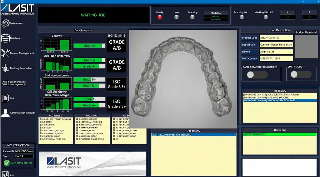
No industrial marking system on medical devices is complete without an integrated automatic verification loop. For aligners, the de facto standard involves an industrial camera positioned downstream of the laser scanner that: (1) reads the marked Data Matrix code and verifies its correspondence with the expected data; (2) measures the quality of the code according to ISO/IEC 15415 (contrast, cell size, geometric deformation); (3) detects the presence of any secondary marks or transparency alterations outside the marking area. In case of an anomaly, the part is diverted to a reject line and the event data is recorded in the ESM with timestamp and defect image-essential documentation for the validation dossier and for the response in case of post-market complaint.
LASIT has developed integrated solutions in this context that combine third-generation UV sources with sub-millimeter resolution vision systems, enabling manufacturers such as industrial dental laboratories and aligner OEMs to achieve OEEs in excess of 95 percent on the marking station, with batch changeover times of less than 10 minutes thanks to automatic laser recipe changeover and optical tray recognition.
Conclusions: UV marking as an enabler of compliance and competitiveness
UV laser marking of transparent aligners sits at the intersection of stringent regulatory requirements, specific material challenges and rapidly growing production demands. Choosing the right technology – 355 nm wavelength, low HAZ photochemical process, integrated verification system – is not a matter of technological preference, but a functional requirement for anyone intending to operate in compliance with MDR, FDA 21 CFR Part 820 and ISO 13485.
The path from first material test to validated production requires application expertise, not just hardware: knowledge of laser-polymer interaction mechanisms, ability to design a repeatable process, experience integrating with clinical data management systems. Those who approach this path with a vendor with an application laboratory, documented testing capabilities, and support for the validation phase significantly shorten time-to-market and reduce the risk of noncompliance.