Every implant screw inserted into bone tissue carries with it a responsibility that goes far beyond surgery: that ofpermanent, verifiable identification throughout the device’s life cycle. A Gr4 or Gr5 titanium implant can remain in place for decades, go through dozens of sterilization cycles, and pass through multiple health care providers. In each of these steps, readability of the UDI – Unique Device Identification – code is not an option but a regulatory requirement.
The enactment of EU MDR 2017/745 and corresponding FDA 21 CFR 830 regulations have made direct marking mandatory for all Class II and III implantable medical devices, including osseointegrated implants, prosthetic abutments, cover screws, and reusable rotary instruments. The problem is technical before it is regulatory: on titanium surfaces 3-5 mm in diameter, curved and intended for repeated sterilization, traditional mechanical etching and pad printing technologies show structural limitations that are difficult to overcome.
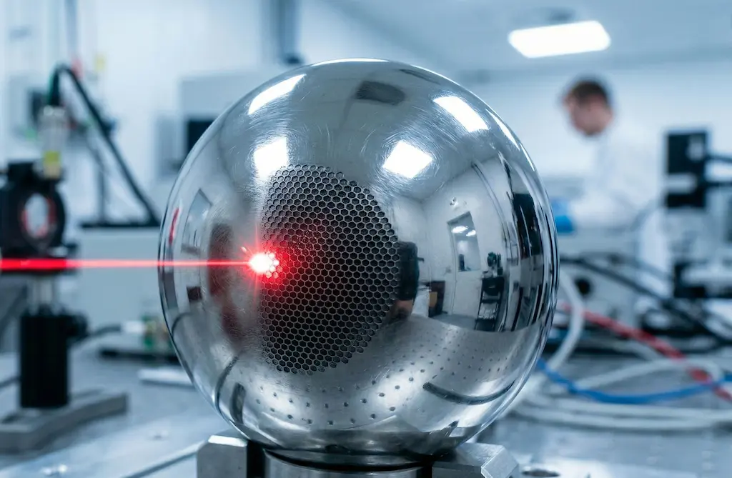
Laser marking-fiber or UV depending on the material and application-is now the benchmark solution for this industry.
Regulatory Requirements: what MDR 2017/745 says and what it implies for the manufacturer
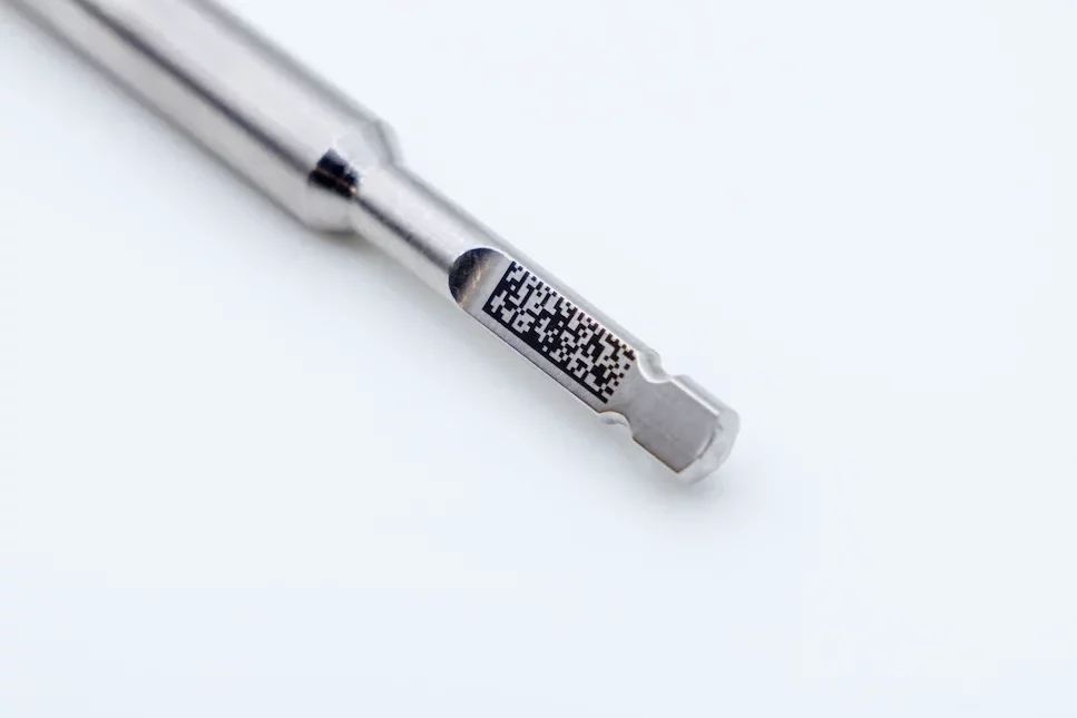
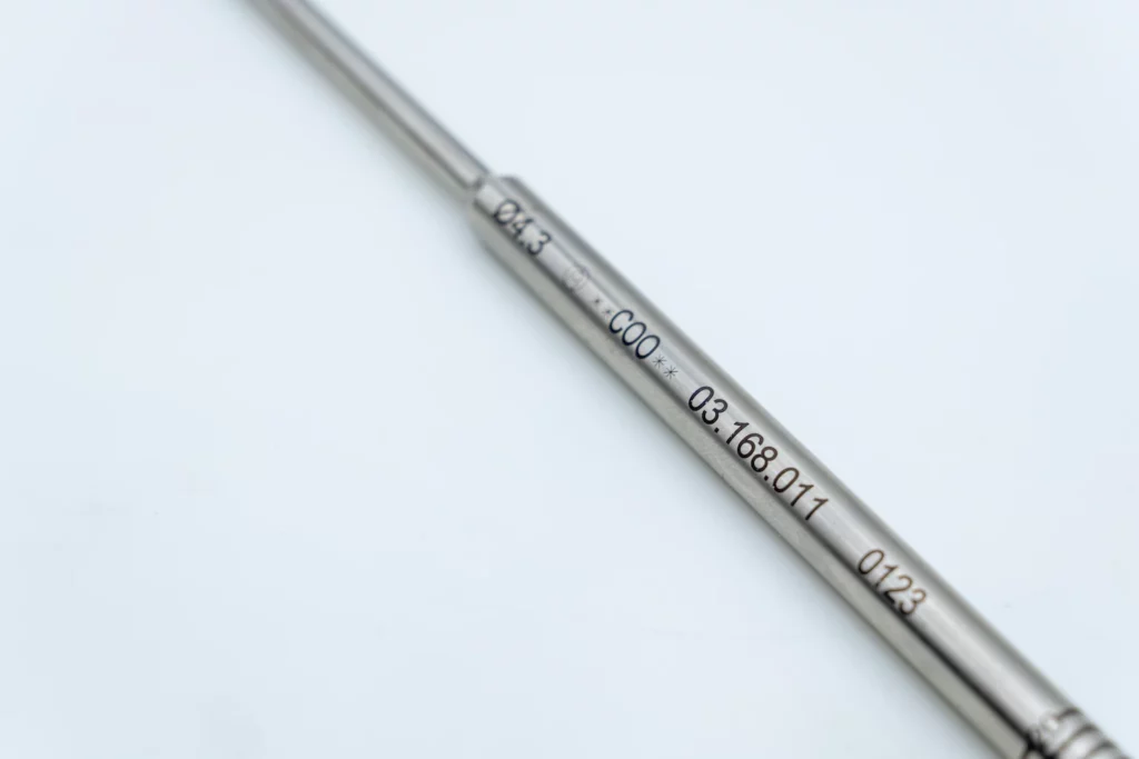
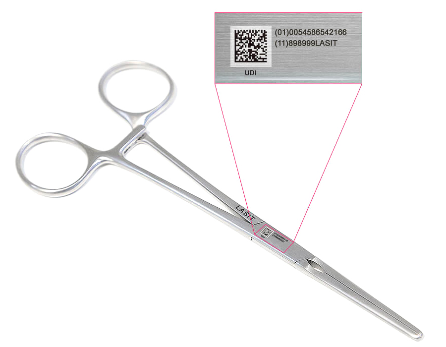
Regulation 2017/745 states that implantable medical devices must bear directly on the surface a UDI-DI (Device Identifier) code in DataMatrix format (ISO/IEC 16022), with a minimum module size of 0.25 mm and minimum quality level ANSI/AIM DPM Grade B. For reusable devices, such as stainless steel or carbide rotary instruments, the marking must survive manufacturer-defined sterilization cycles-typically 500+ autoclave cycles at 134 °C according to EN ISO 17665.
This imposes a definite physical constraint: the code cannot be applied with inks or surface coatings, as these degrade both chemically (saturated steam, peracetic acid, UV radiation in advanced disinfection cycles) and mechanically (abrasion, ultrasonic cleaning). The manufacturer is required to validate residual readability according to ISO 15223-1 and document it in the Technical File according to Annex II MDR.
At the level of clinical traceability, the Ministerial Decree Oct. 7, 2021, transposes MDR and requires that the UDI be associated with the patient’s electronic medical record and the national implant registry (BDNPM). This means that an illegible code during a surgical revision or explant is not just a quality issue: it is a systemic noncompliance involving the manufacturer, the healthcare facility, and, in the case of adverse events, the competent authority.
Why Laser Marking Outperforms Mechanical Engraving and Pad Printing
Traditional alternatives to laser marking-electroengraving, micro-percussion, and pad printing-dominated the industry until the early 2000s, but they have physical limitations that cannot be circumvented when working on implantable medical devices.
Mechanical engraving and micropercussion
Vibratory tip or percussion systems create identation by plastic deformation of the material. On Gr4 titanium this generates sub-surface micro-cracks with depths varying between 15 and 80 µm depending on alloy hardness and angle of attack. These discontinuities represent preferential sites of crevice corrosion initiation in the physiological environment and, on rotating instruments, trigger points for mechanical fatigue. Added to this is the practical impossibility of achieving resolutions below the 0.4 mm modulus without risking compromising the geometry of the component.
Pad printing and screen printing
Ink processes – pad printing for three-dimensional surfaces, screen printing for flat surfaces – apply organic layers with typical thicknesses of 5-25 µm. Sterilization resistance is limited: after 50-100 autoclave cycles, the adhesion of UV-curable inks is progressively reduced by differential thermal expansion cycles. For implantable Class III devices, MDR explicitly prohibits the use of non-biocompatible inks as permanent markers, as they can release extractable substances in aqueous environments at physiological pH.
The laser advantage: physical modification of the surface
Laser marking operates through a permanent modification of the surface metallurgical structure without addition of external material. In the controlled oxidation regime (laser anodizing), a pulsed beam at 1064 nm on titanium locally induces a layer of titanium dioxide TiO₂ with controllable thickness between 20 and 200 nm: the interferential effect on light produces a highly readable visual contrast without removing material or altering the mechanical properties of the bulk. In the ablative regime, the laser removes layers of 1-3 µm per pulse, producing reliefs or depressions with coded geometry readable by optical scanners at any angle of illumination.
The result is a marking integrated into the structure of the material, biocompatible by definition since it is composed exclusively of the base alloy elements, resistant to temperature, vapor and chemicals with the same durability as the component.
Process Physics: Fiber vs. UV, When to Use Which Source.
The choice of laser source is not stylistic but depends on the optical and thermal properties of the substrate, dimensional requirements, and the final application.
| Parameter | Fiber 1064 nm | Green 532 nm | UV 355 nm |
| Absorption on Ti | High (60-75%) | Very High (>80%) | Excellent (>90%) |
| Spot size min. | 20-30 µm | 15-20 µm | 8-15 µm |
| HAZ (Thermal Zone) | Moderate | Reduced | Minimal (<5 µm) |
| Main application | Titanium, stainless steel | Reflective alloys | Plastics, ceramics |
| Marking speed | 1,000-3,000 mm/s | 500-1,500 mm/s | 300-800 mm/s |
| Operating power | 10-50 W | 5-20 W | 3-10 W |
| Investment cost | Low-medium | Medium | Medium-high |
For the vast majority of commercially pure titanium (Gr2, Gr4) or Ti-6Al-4V alloy implants, the pulsed fiber laser with 1064 nm wavelength represents the operational optimum: high absorption on metal, marking speed compatible with mass production (up to 3,000 components/shift for small screws), low operating cost due to the absence of optical consumables. The 355 nm UV system becomes preferable when marking components made of PEEK, zirconia, or thermoplastic polymers used in dental prostheses and surgical guides: the short wavelength allows cold photonic ablation with HAZ less than 5 µm, eliminating any risk of thermal degradation of polymer matrices.
Technical Challenges: Biocompatibility, Micro-cracks, and Readability on Complex Surfaces
Laser marking on medical devices introduces three orders of technical challenges that require a rigorous parametric approach, different from that applied in other industries.
Maintaining the biocompatibility of titanium
Titanium derives its biocompatibility from the passive TiO₂ layer that naturally forms on the surface. A non-optimized laser process can locally alter the crystal structure of this layer, introducing nonstoichiometric phases that reduce corrosion resistance in a physiological environment. The correct parameterization involves power densities between 10⁸ and 10⁹ W/cm² with pulse widths between 20 and 100 ns, so as to operate in the regime of controlled oxidation rather than deep ablation. Post-process XPS verifications confirm the exclusive presence of TiO₂ rutile in the surface layer when the parameters are properly calibrated.
Control of micro-cracks
The risk of micro-cracks-absent in laser anodization regime, present in poorly calibrated deep ablation-is monitored by cross-sectional metallographic inspection with atomic force microscope (AFM) or SEM. In our experience with implant manufacturers, the most popular acceptance criterion involves sub-surface thermal alteration depths of less than 10 µm and no detectable cracks at 500x. This is achieved by optimizing the combination of repetition frequency (20-100 kHz) and pulse overlap (50-70%).
Readability on curved and small surfaces
Abutments and cover screws have cylindrical geometries with diameters between 1.8 and 6 mm. On these surfaces, the laser focus varies along the axial direction of the component, producing variations in energy density that result in contrast unevenness. The technical solution is twofold: use of telecentric F-theta optics with focal lengths appropriate to the working range, combined with motorized rotating mounts that develop the cylindrical surface during marking. This allows DataMatrix Grade A (ANSI/AIM DPM) quality to be achieved even on 0.25 mm modules on surfaces with curvature up to 90°.
Typical Workflow: from Data Definition to Metrological Validation.
A laser marking process that is GMP (Good Manufacturing Practices) compliant and traceable according to ISO 13485 consists of sequential steps with documented checkpoints. The diagram below illustrates the standard flow for an implantable device manufacturer.
| Phase | Description and document output |
| Data definition | Engineering defines UDI-DI + UDI-PI structure (lot, series, date of manufacture) according to GS1 or HIBCC. Output: approved marking specification in PLM/ERP system. |
| Layout generation | Marking software (e.g., CADlink, EZCAD) receives feed from MES/ERP and generates work file with DataMatrix ECC200 symbology. Automatic checksum verification. |
| Machine setup and qualification | Definition of laser parameters (power, frequency, speed, n° passes). Execution on qualification samples. DataMatrix grade verification with certified reader (Cognex, Microscan). Output: IQ/OQ report. |
| Mass production | Marking on dedicated fixtures with integrated inline code presence and correctness check (vision system). Each marked part receives unique ID recorded in the MES system. |
| Quality control | Sample verification with verification reader (not simple scanner) according to ISO/IEC 15415 or AIM DPM. Minimum grade accepted: B (ideal A). Measurement of contrast, cell size, uniformity. |
| Metrological validation | For Class II/III devices: full process validation according to ISO 13485 §7.5.6. Samples subjected to stress test (500 autoclave cycles, simulated immersion for 30 days). Documentation in the QP and MDR Technical File. |
| UDI-Database Registration | UDI upload in EUDAMED (EU) and GUDID (FDA). Lot/series association to compliance documentation. Two-way traceability enabled. |
Key to this process isMES-laser integration: the marking system does not operate as an autonomous island but receives data directly from production management, eliminates the risk of manual transcription errors and ensures consistency between what is physically marked and what is recorded in the traceability database. Systems such as our FlyMark are natively designed for this integration, with OPC-UA, Profinet and REST API communication protocols that enable dialogue with the main MESs found in medical device factories.
Clinical Applications: Implants, Rotating Instruments and Dental Laboratories
The application landscape of laser marking in dentistry is broader than implantology alone would suggest. Three areas deserve specific analysis.
Manufacturers of implants and prosthetic components
For osseointegrated implants, abutments and cover screws, fiber laser marking in an anodized regime is the standard process. Small screws (diameter 1.8-3.5 mm, length 6-16 mm) are marked in multi-position fixtures at rates of 200-600 pieces/hour depending on code complexity and line configuration. The surface quality of the implant is not altered: surfactant tests and Ra roughness analysis on SLA- and RBM-treated surfaces confirm that laser marking confined to the smooth cervical zone does not change the roughness profile of the osseointegrative zones.

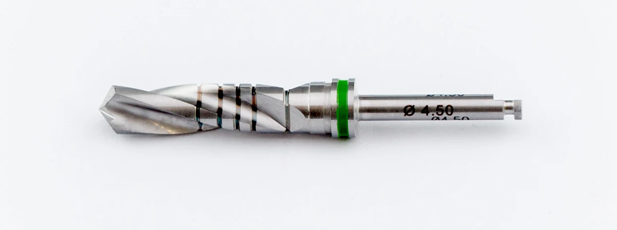
Reusable rotary instruments
AISI 440C or HSS stainless steel burs, rasps, chisels, and NiTi endodontic files represent a category with different specifications: harder materials, often helical geometries, and mandatory instrument traceability throughout the cycle of use in the clinic. On these components, the fiber laser operates in controlled ablative mode, producing negative markings (reliefs within protected cavities) to preserve readability even after aggressive mechanical cleaning. Typical ablation depth is 5-15 µm with tract widths of 30-50 µm.

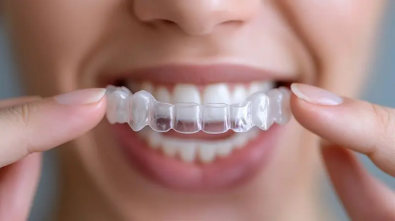
Dental laboratories and clinics
One growing segment involves the marking of custom prosthetic artifacts: zirconia (Y-TZP) crowns, milled titanium milling bars, and stereolithographed resin models destined for long-term archives. In these operating environments-often laboratories with small floor areas and non-automation trained staff-the answer is compact Benchtop laser systems with integrated safety enclosure, Class 1 laser classification in use, and simplified operator interface. Our approach with customers in this segment involves systems with a footprint of less than 0.5 m² and an operational learning cycle of less than 2 hours, while maintaining full compatibility with the export formats of major dental CAD/CAM software (3Shape, exocad, Dental Wings).
Final Considerations
Permanent laser marking has become an infrastructural requirement for any manufacturer operating in the dental medical device market. It is not just one technological choice among other equivalents: MDR 2017/745 and FDA regulations define durability and legibility requirements that only physical modification of the surface-not the application of external material-can verifiably ensure throughout the life cycle of the device.
Source selection (1064 nm fiber vs. UV 355 nm), process parameterization, and integration into the MES production flow are not implementation details-they are the factors that determine the difference between a marking that passes validation on the first try and a process that requires months of iteration. Investment in proper process design-from substrate analysis to qualification according to ISO 13485 to UDI data management-returns measurable value in reduced audit time, elimination of rework, and building a robust technical dossier.