A dental implant goes through a complex life cycle: from casting or CNC milling of the titanium blank, through surface treatments (sandblasting, acid etching, HA coating), to sterilization, bagging, and surgical insertion. At each of these stages, individual component traceability is not an option, but a legal requirement. The European Medical Device Regulation MDR 2017/745, fully applicable from May 2021, requires the implementation of the Unique Device Identification (UDI) system for all medical devices placed on the European market, with mandatory registration in EUDAMED.

For manufacturers of implants, abutments, implant drills, and rotary instruments, this translates into a precise technical question: how to apply a permanent, machine-readable identifier to millimeter-sized metal surfaces that survives hundreds of autoclave sterilization cycles at 134°C and in no way compromises the biocompatibility of the material? The answer the industry has identified with growing acceptance is laser marking, in fiber, UV or green declination depending on the substrate and level of detail required.
Regulatory requirements, technical constraints, and limitations of traditional solutions
The regulatory framework: UDI, MDR and ISO 13485
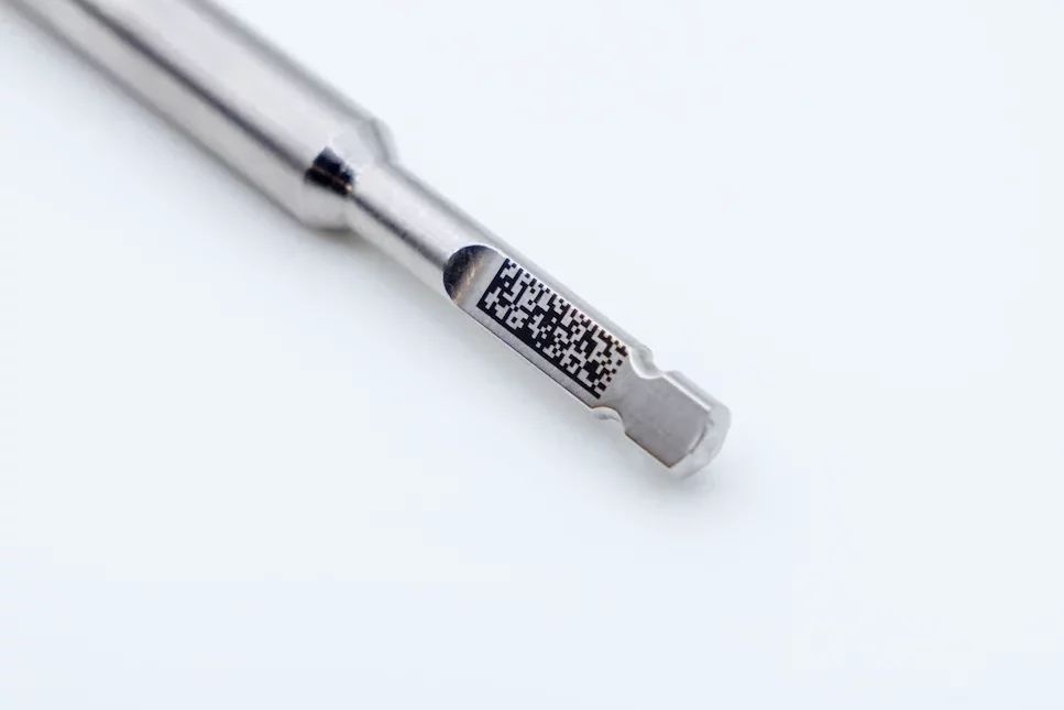
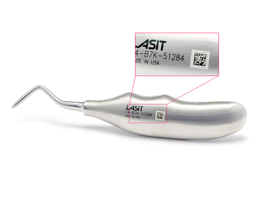
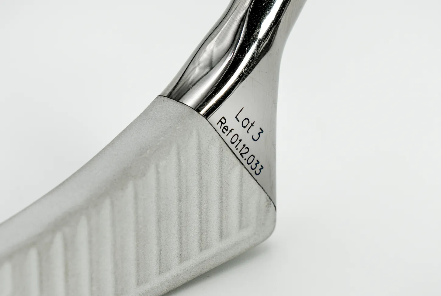
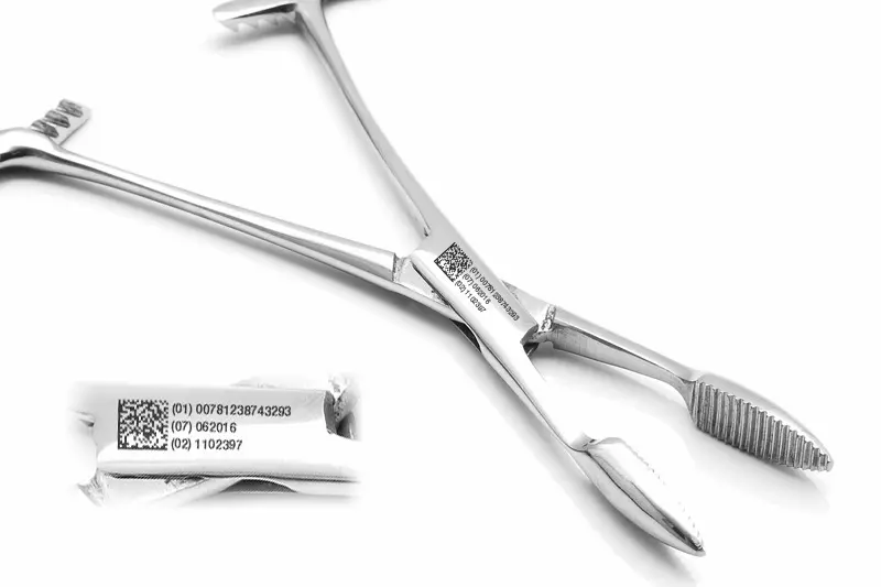
The UDI system has two components: the Device Identifier (UDI-DI), which identifies the model and manufacturer, and the Production Identifier (UDI-PI), which includes lot, serial number and expiration date. Both must be on the label and-for reusable devices such as surgical instruments-directly on the device in Machine Readable Form (MRF). The gold standard for coding is the DataMatrix ECC200, capable of holding more than 2,000 alphanumeric characters in an area that on dental instruments is often reduced to less than 4×4 mm, requiring symbol cells as small as 150-200 µm on a side.
The required quality management system is ISO 13485:2016, which requires complete validation of the marking process according to an IQ/OQ/PQ (Installation Qualification, Operational Qualification, Performance Qualification) approach. Any variation in laser parameters must be justified and documented. The process must be repeatable and reproducible with Cpk ≥ 1.33 on critical features-degree of code readability, surface roughness in the marked area, absence of metallographic alterations.
The limitations of pre-laser technologies
Before laser marking became affordable even for medium and small batches, dental manufacturers had basically two alternatives: mechanical engraving by pantograph or diamond tools, and pad printing with special inks. Both have structural criticalities that become untenable with MDR requirements.
Mechanical etching introduces surface stresses by plastic deformation: on grade 4 or grade 23 titanium (Ti-6Al-4V ELI), this can trigger microcracking near the marking, creating trigger sites for crevice corrosion in the oral environment. The induced roughness (typically Ra > 0.4 µm in the etched area) promotes bacterial colonization, which on peri-crestal implant surfaces is a critical risk factor for peri-implantitis. Pad printing, on the other hand, is not allowed at all for permanent markings on reusable devices: inks do not withstand saturated steam sterilization cycles at 134°C/3 bar, and regulations explicitly prohibit dyes or pigments that are not biocompatible in contact with tissue.
Laser marking for dental medical devices: physical mechanism and key advantages
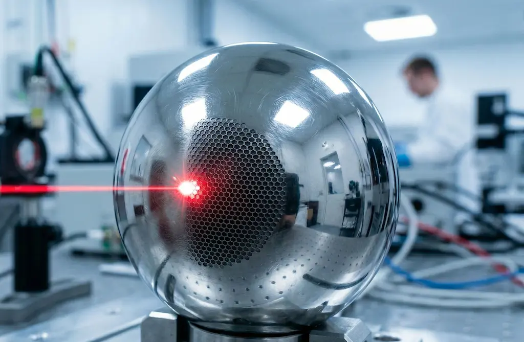
The laser acts on the metal through a mechanism of photon-crystal lattice interaction that differs markedly from mechanical removal. The beam energy is absorbed by the metal’s conduction electrons and transferred to the lattice in times on the order of picoseconds (for nanosecond pulsed sources) or femtoseconds (for ultrashort sources). The result depends on the fluence applied: below the ablation threshold, the material undergoes an oxidative surface modification-a phenomenon that on titanium produces the characteristic blackening by formation of a TiO₂ layer of controllable thickness between 20 and 200 nm. This oxide is not a contaminant: it is chemically identical to the passive layer that makes titanium biocompatible, but with a thickness optimized for visual absorption that generates the optical contrast necessary for reading the DataMatrix.

Yb:YAG fiber sources (1064 nm) are the predominant choice for stainless steel (AISI 316L, ISO 5832-1) and cobalt-chromium alloys: the good absorbance of these materials in the infrared, combined with peak powers of up to 15 kW in Q-switch mode, allows high marking speeds-8,000-10,000 mm/s with high-inertia galvanometric heads-while keeping the thermal influence zone within 3-5 µm. The 355 nm UV laser (third harmonic Nd:YAG) is preferred for high-purity titanium, PEEK and biocompatible polymers: the shorter wavelength ensures 10-15 µm spots with energy per pulse typically less than 100 µJ, further reducing thermal stress and enabling markings on area < 2×2 mm without geometric distortion. The 532 nm green laser finds application on materials with high infrared reflectivity, such as some highly polished steels intended for aesthetic prosthetic components.
An aspect often overlooked in technical evaluations is the actual depth of substrate alteration. SEM-EDX analyses conducted on titanium grade 23 samples tagged with fiber lasers (parameters: 20 W, 100 kHz, speed 2000 mm/s, 3 passes) show that the zone of metallurgical alteration is confined to within 4-6 µm of the surface, with absence of micro-cracks at 5000× resolution and XRF composition unchanged from the base material. This data is critical for the documentation of the technical dossier required by Annex II of the MDR.
The picosecond source: why it changes the rules for medical devices
Within the category ‘laser marking’ there is a fundamental physical distinction that is often flattened in the commercial literature: the difference between nanosecond (ns ) and picosecond (ps) pulse sources. This is not a quantitative variation of the same phenomenon, but a qualitative change in the mechanism of beam-matter interaction-with direct consequences for the metallurgical quality of the marking, the integrity of biocompatibility, and application possibilities on critical materials and geometries.
A typical ns Q-switch laser delivers pulses of 10 to 200 ns with peak powers on the order of 10 to 15 kW. During that time-long compared to the time constants of thermal phenomena in metal-the energy absorbed by the conduction electrons transfers to the crystal lattice and produces localized melting: the material melts, oxidizes (in the case of titanium producing the contrast-generating TiO₂ layer), then solidifies. The result is technically excellent for the vast majority of applications, but leaves a thermal alteration zone (ZAT) of 3-8 µm and a thin layer of remelted material (recast layer) of 0.5-2 µm at the edges of the marking.

A ps source delivers pulses from 2 to 15 picoseconds-that is, 10-100 times shorter. With the same energy per pulse, peak power reaches up to 500 kW, generating enough photon density to triggerdirect multipotonic ionization of the lattice: atoms are removed from the substrate without passing through the liquid phase. This mechanism, called cold ablation or nonthermal ablation, produces a ZAT of less than a micrometer-at the limit of detectability even with high-resolution SEMs-and the almost complete absence of recast layers. The resulting marking has Ra roughnesses between 0.05 and 0.25 µm in the ablated zone, as opposed to the 0.3-0.8 µm typical of a well-optimized ns process.
Where the picosecond becomes superior: the critical application cases
For most marking applications on grade 4 titanium or AISI 316L steel implants, a well-configured ns system produces ISO 15415 grade A/B compliant results and fully meets MDR requirements. The picosecond becomes the technically superior-and in some cases the only viable-choice in four specific scenarios.
The first is marking on oxide zirconia (Y-TZP), the reference material for monolithic crowns, cover screws in esthetics, and ceramic abutments. With ns sources, thermal energy transferred to zirconia can induce phase transformation from tetragonal to monoclinic-a phenomenon that reduces the fracture toughness of the material by up to 30 percent in the area adjacent to the marking. The ps laser, operating in the cold ablative regime, selectively removes the material without triggering this phase change, fully preserving the mechanical properties of the ceramic. This result can be verified by micro-Raman analysis on the marked area.
The second critical scenario concerns SLA and SLActive (sandblasted large grit acid-etched) implant surfaces, where sub-micrometer nanotopography is the determining factor for osseointegration. A focused ns beam, even at low fluence, can flatten this morphology in the irradiation area by diffuse heat. The picosecond spot size-typically 5-15 µm with M² < 1.3-allows the DataMatrix to be placed in a flat area of the implant neck without interfering with the nanotopography of the coils, as long as the layout is designed with sufficient quiet zone from the surface treatments.
The third case concerns grade 23 titanium devices (Ti-6Al-4V ELI) for cyclic loading applications-such as fixtures for zygomatic implants or superstructure bars-where fatigue strength is a critical safety parameter. The absence of recast layer in the ps process eliminates a major cause of fatigue crack initiation at the marking. Fatigue life analyses on specimens marked with ns and ps processes at the same geometry show fatigue limit increases in the range of 15-25% in favor of the ps process, a finding relevant to the drafting of the MDR Annex II technical dossier.
The fourth emerging scenario is marking on PEEK and high-modulus biocompatible polymers (PAEK, PI): the 355 nm UV ps laser produces extremely clean photochemical-mechanical ablation, without the peripheral carbonization zone that even the UV ns laser can generate on long-chain polymers. The result is sharp contrast, edges defined to 5 µm, and no residues that could be classified as surface contaminants in the sterilization process.
| Parameter / Criterion | Laser ns (1064 nm Q-switch fiber) | Ps laser (1064 / 532 / 355 nm) |
| Pulse Duration | 10 – 200 ns | 2 – 15 ps (×10-100 shorter) |
| Peak power (at the same energy) | ~10 – 15 kW | up to 500 kW – higher photon density |
| Dominant mechanism | Thermal: melting + surface oxidation | Ablative: direct ionization (cold plasma), minimal melting |
| Zone of thermal alteration (ZAT) | 3 – 8 µm on Ti grade 23 | < 1 µm – at the limit of SEM detectability |
| Recast layer (recast material) | Present: 0.5 to 2 µm, micro-inclusion risk | Absent or < 0.2 µm: clean ablation |
| Micro-cracks on Ti-6Al-4V alloys ELI | Possible parametric out-of-window | Not detectable at 10,000× SEM even at high fluences |
| Ra zone roughness marked | 0.3 – 0.8 µm (depends on speed/frequency) | 0.05 – 0.25 µm – nearly specular surface post-marking |
| Contrast DataMatrix (ISO 15415) | Regular A/B grade on Ti and CoCr | Grade A stable on Ti, CoCr, superalloy steels, PEEK, zirconia |
| Applicability on zirconia (Y-TZP) | Limited: thermally altered layer degrades mechanical strength | Excellent: cold ablation without crystal phase alteration |
| Applicability to SLA/SLActive treated surfaces. | Risk of flattening sub-micrometric morphology. | Small spot (< 10 µm) allows marking on flat areas without touching nanotopography |
| Marking speed | High: 8,000 to 10,000 mm/s | Medium-high: 3,000 – 8,000 mm/s (lower energy/pulse requires more passes or lower speed) |
| Typical system investment | 35.000 – 80.000 € | 70,000 – 150,000 (ps source still premium) |
| TCO over 7 years | Low – MTBF source > 100,000 h | Low – similar structure, amortized source cost |
Table 2-Technical comparison ns vs ps for dental medical device applications. ZAT and Ra data are average values on titanium grade 23; vary depending on operating parameters.
The cost gap between ps and ns sources has narrowed significantly over the past five years: 1064 nm ps systems are now available in the €70,000-150,000 range, compared with €35,000-80,000 for an equivalent ns system. Over a 7-year horizon and volumes of 30,000+ devices/year, the difference in cost per tagged part is less than €0.05, amply justified by the advantages in terms of metallurgical quality, expansion of the application portfolio (zirconia, SLA, polymers), and simplification of the validation dossier-where the documented absence of ZAT and recast layer significantly reduces the number of SEM analyses required in the OQ plan.
Technical specifications and system configuration
The following table summarizes the key operating parameters of laser configurations typically used in dental medical device manufacturing, based on LASIT’s experience with orthopedic and dental customers.
| Parameter | Specifications/Operating range |
| Available laser sources | Fiber ns Yb (1064 nm) | UV ns (355 nm) | Green (532 nm) | Picosecond (1064 / 532 / 355 nm) |
| Pulse duration – ns fiber | 10 – 200 ns (Q-switch); peak power up to 15 kW |
| Pulse duration – picosecond | 2 – 15 ps; peak power up to 500 kW (at the same average energy) |
| Average fiber power ns | 20 W – 100 W |
| Average power source ps | 10 W – 50 W (energy/pulse 10 – 500 µJ) |
| Spot size (fiber ns) | 20 – 100 µm (interchangeable lenses) |
| Spot size (ps) | 5 – 30 µm – M² factor < 1.3 guaranteed |
| ZAT – ns fiber on titanium | 3 – 8 µm (depends on fluence and velocity) |
| ZAT – ps on titanium | < 1 µm (ablative-cold regime, no melting) |
| Scanning speed | Up to 10,000 mm/s (galvo head, both sources) |
| Depth of titanium marking | < 5 µm (oxidation ns) | < 2 µm selective ablation ps |
| Repeatability positioning | ± 5 µm |
| Standard work area | 100×100 mm – 300×300 mm (f-theta optics) |
| Codes readable after sterilization | DataMatrix ECC200, QR, 1D Barcode |
| Reference standard | ISO 13485, MDR 2017/745, UDI EUDAMED, FDA 21 CFR Part 820 |
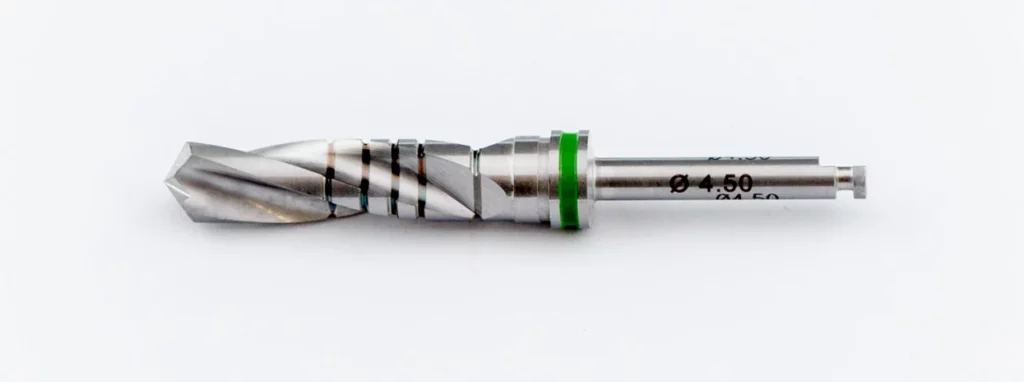
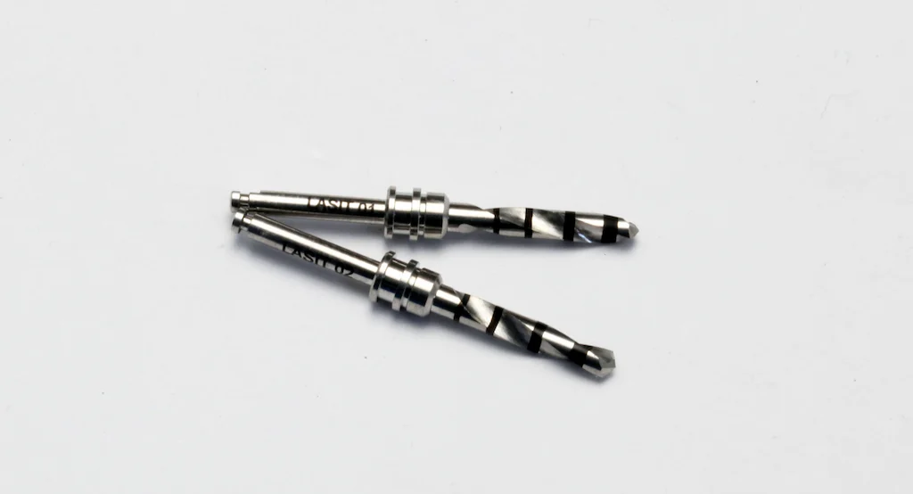
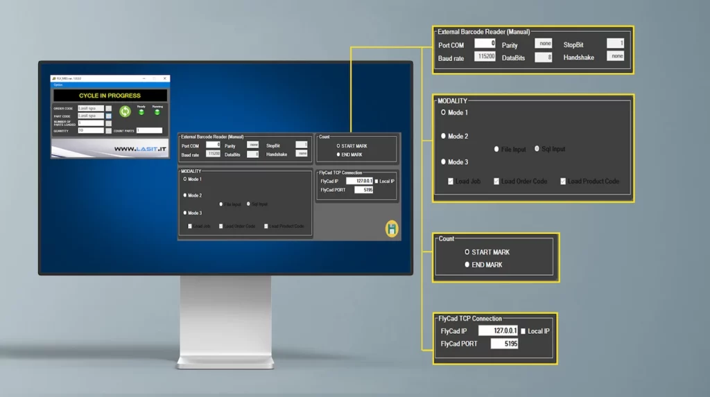
In terms of hardware, systems intended for medical device manufacturing require specific configurations compared to general industrial applications. The three-axis (3D) galvanometric scanning head allows constant focus on conical or cylindrical surfaces-such as the body of an implant with a helical profile-within ±15 mm vertical travel without mechanical repositioning of the part. For more complex geometries (shank drills, endodontic instruments), the optimal solution involves a rotary axis synchronized electronically with the galvo head, allowing continuous cylindrical development marking with 0.1° angular resolution. The control software must handle automatic serialization with IP augmentation, bidirectional communication with the company’s MES via OPC-UA or API REST, and automatic generation of the marking record in EUDAMED-compliant format.
Technical comparison: laser vs mechanical engraving vs pad printing
The choice of marking technology for medical devices is not solely an economic decision: it has direct implications for regulatory compliance, product durability and clinical safety. The following table systematizes the most relevant comparison criteria for technical and regulatory decision makers.
| Criterion | Fiber laser marking | Mechanical engraving | Tampography |
| Surface integrity | Thermal stress < 5 µm; no micro-cracking if correct parameters | Micro-cracks from plastic deformation (Hertz); Ra > 0.4 µm | No mechanical damage |
| Biocompatibility (Ti) | TiO₂ oxide layer intact or controlled (passive blackening) | Tool contamination (Co, Cr), crevice corrosion risk | Ink residue; not MDR compatible |
| Sterilization resistance | Permanent – unaltered after 1000+ autoclave cycles 134°C | Permanent but degradation edges over time | Degrades after 5-20 cycles; not allowed on MDR plants |
| DataMatrix Readability | ISO 15415 A/B grade warranted on Ti, CoCr, PEEK | 1D codes only; DataMatrix difficult on curved surfaces | Not applicable to DataMatrix |
| Geometric flexibility | High: cylindrical, spherical, helical surfaces with rotating axis | Low: only flat surfaces or simple cylindrical development | Average: only regular surfaces |
| Process traceability | Full: digital log power, speed, energy by code | Limited: tool and force data not always recordable | Absent |
| Total cost of ownership | Low TCO: source > 100,000 h MTBF, no consumables | Low initial; high on volume (tool wear) | Low initial; high volume (inks, maintenance) |
The total cost of ownership item deserves a closer look. A fiber laser system for medical applications has an indicative initial investment of €35,000-80,000 depending on the configuration, but an extremely low operating cost: the Yb doped fiber source has an MTBF of more than 100,000 hours, requires no process gas, and has no consumables in the strict sense of the term. On a volume of 50,000 installations/year, the marking cost is in the range of €0.03-0.08/piece, including depreciation, energy and scheduled maintenance. Mechanical solutions have seemingly lower costs per part, but they require periodic tool renewal, fixture recalibration, and do not guarantee process traceability-an element that becomes a critical nonconformity in ISO 13485 audits.
Technical challenges: biocompatibility, micro-cracks, and readability on complex surfaces
Titanium: a material that rewards precision
Medical-grade titanium (ASTM F67 for commercially pure Grade 4, ASTM F136 for Ti-6Al-4V ELI alloy) is an extraordinarily surface-reactive material. Its biocompatibility is critically dependent on the integrity of the passive oxide layer: any process that alters the surface composition, introduces metal contaminants, or creates geometric discontinuities can reduce osseointegration and increase the risk of corrosion in a biological environment.
The most critical laser parameter for preserving biocompatibility is not average power, but fluence per pulse (J/cm²). With Q-switch fiber lasers operating at 1064 nm, the safe operating window for titanium grade 4 is typically between 0.5 and 3.5 J/cm² per pulse, with repetition frequencies of 50-200 kHz and scanning speeds of 500-3000 mm/s. Below 0.5 J/cm² the marking is insufficiently contrasted (ISO 15415 grade < C); above 4 J/cm² there is a risk of material removal with borer formation and spindle projections. With ps sources, the thresholds change profoundly: the operating window widens, as the cold ablative mechanism is inherently less sensitive to fluence fluctuations in the 0.3-5 J/cm² range, and most importantly, borer and recast layer formation is absent by physical definition-not by parametric optimization, but by the very nature of the interaction.
Surgical steels and CoCr alloys: the issue of chromium
For AISI 316L steels and cobalt-chromium alloys used for burs and surgical instruments, the primary challenge is not micro-cracking but surface chromium diffusion induced by poorly controlled thermal cycling. Excessive energy per pulse-above the ablation threshold-can cause preferential evaporation of chromium, depleting the surface CrO₃ layer that provides corrosion resistance and increasing the potential for release of metal ions into the biological environment. This phenomenon is detectable by X-ray Photoelectron Spectroscopy (XPS) analysis and must be part of the process validation plan for reusable instruments classified as Class IIa or IIb according to MDR.
PEEK and polymers: where the UV laser makes a difference
PEEK (polyetheretherketone) is the emerging material for dentures, temporary abutments and surgical guides. Its marking with IR fiber lasers is problematic: absorption at 1064 nm is low and requires high fluences that carbonize the polymer, generating blackened areas with low adhesion and potential particulate release. The UV laser at 355 nm, with its predominantly photochemical-ablative interaction (breaking molecular bonds rather than thermal fusion), produces clean, defined markings with sharp edges and no thermal halo-verifiable by optical microscopy at 200× without the need for SEM.
Conclusions: laser marking as quality infrastructure, not cost
Permanent laser marking for dental medical devices has gone through a decade-long transition from a specialized technology to a system requirement. The MDR/UDI requirement has accelerated this convergence, but the underlying technical reason is deeper: no alternative technology simultaneously guarantees permanence, biocompatibility, geometric accuracy, and process traceability at the level required by modern clinical practice.
Within the laser family, the most relevant distinction for the coming years is between nanosecond and picosecond sources. The former remain the correct and mature choice for the vast majority of applications on titanium and surgical steels in high volumes, with excellent TCO and established validation processes. Ps sources become the technically superior-and in some cases mandatory-choice on zirconia, SLA/SLActive surfaces, highly critical cyclically loaded alloys, and high modulus polymers: four categories that cover an increasing share of the production portfolio of high-end dental manufacturers.
There are six key points for informed technical evaluation. The choice of wavelength (1064, 532, 355 nm) and time regime (ns vs ps) is not interchangeable: it depends on material, geometry and dimensional requirements of the code. IQ/OQ/PQ validation should be planned at the time of purchase, not a posteriori. Fluence per pulse is the primary control parameter of biocompatibility, and ps widens the safe operating window. Integration with MES via OPC-UA or REST API is a necessary condition for EUDAMED traceability. The TCO of ps is justifiable as low as 30,000 parts/year if the portfolio includes zirconia or treated surfaces. Finally, LASIT supports dental medical device manufacturers in the entire implementation journey-from optimal source selection to ISO 13485 validation, from MES integration to operator training. Contact our applications team for a test session on your specific material and geometry.